
Processing apparatus

Pending Publication Date: 2022-11-17
DISCO CORP
View PDF0 Cites 0 Cited by
  • Summary
  • Abstract
  • Description
  • Claims
  • Application Information

AI Technical Summary

Benefits of technology

The patent describes a holder that can hold a workpiece without touching it. It can apply a strong negative pressure to the workpiece based on its thickness.

Problems solved by technology

According to the disclosed delivery method, however, if an air ejection face, i.e., an end face, of the non-contact-type suction holder is spaced too far from the workpiece, the non-contact-type suction holder fails to apply a negative pressure to the workpiece.
For example, in situations where workpieces are available in a variety of thicknesses ranging from 3.0 to 5.0 mm, if the non-contact-type suction holder is constantly set to a position for holding workpieces that are 3.0 mm thick under suction, then the non-contact-type suction holder is likely to fail to apply a sufficient negative pressure to workpieces that are 5.0 mm thick, and hence to unload those workpieces from the processing apparatus.

Method used


Image

  • Processing apparatus
  • Processing apparatus
  • Processing apparatus

Examples


first embodiment

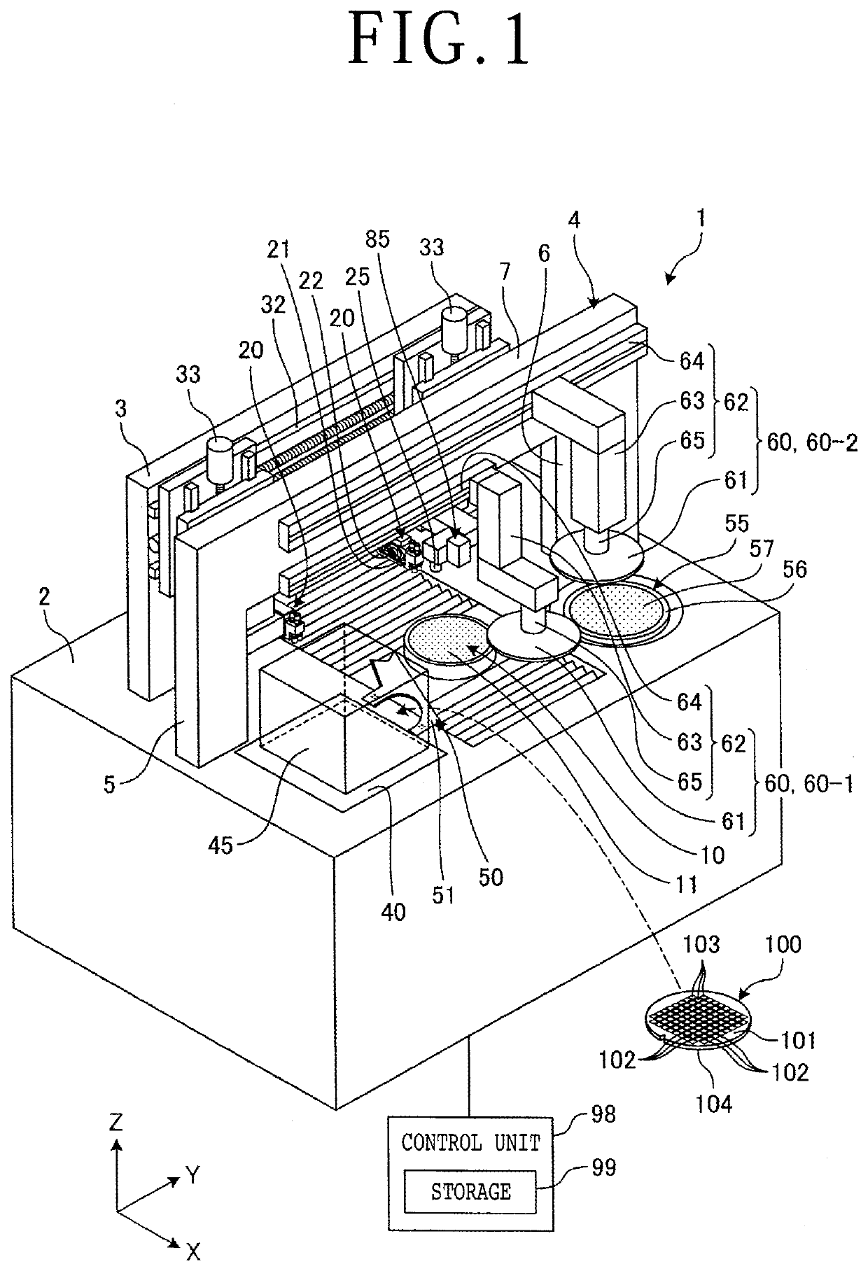
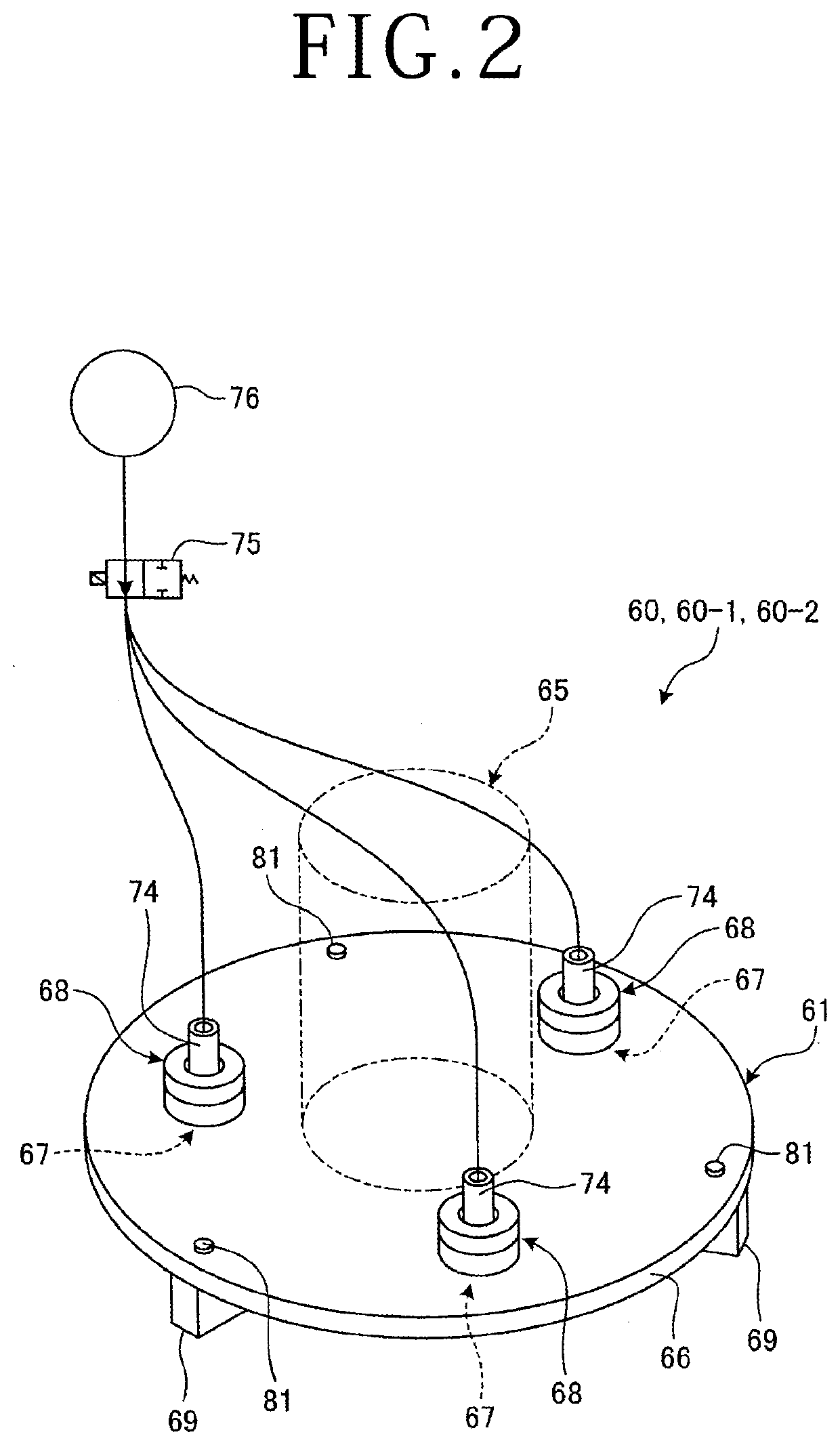
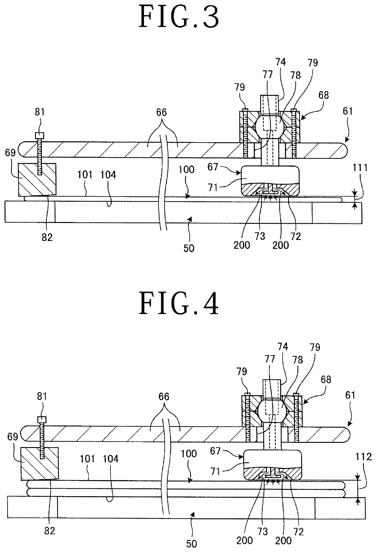
[0016]A processing apparatus 1 according to a first embodiment of the present invention will be described below with reference to FIG. 1. FIG. 1 illustrates, in perspective, a structural example of the processing apparatus 1 according to the first embodiment. FIG. 2 illustrates, in perspective, a structural example of a delivery unit 60 of the processing apparatus 1 illustrated in FIG. 1. FIGS. 3 and 4 illustrate, in cross section, a manner in which the delivery unit 60 of the processing apparatus illustrated in FIG. 1 operates. FIG. 5 illustrates a structural example of a measuring unit 85 of the processing apparatus 1 illustrated in FIG. 1. FIG. 6 illustrates, in cross section, the manner in which the measuring unit 85 of the processing apparatus 1 illustrated in FIG. 1 operates. As illustrated in FIG. 1, the processing apparatus 1 includes a chuck table 10, a pair of processing units 20, a cassette rest 40, a loading / unloading unit 50, a cleaning device 55, a delivery unit 60, a ...

second embodiment

[0054]A processing apparatus 1 according to a second embodiment of the present invention will be described below. The processing apparatus 1 according to the second embodiment is different from the processing apparatus 1 according to the first embodiment in that the measuring unit 85 includes an optical sensor, rather than a back pressure sensor. Other details of the processing apparatus 1 according to the second embodiment are identical to those of the processing apparatus 1 according to the first embodiment. Those identical details are denoted by identical reference characters and will be omitted from description.

[0055]The measuring unit 85 according to the second embodiment includes an irradiator for applying a laser beam to the holding surface 51 of the loading / unloading unit 50 or the face side 101 of the workpiece 100 held on the holding surface 51, and a beam detector for detecting a beam reflected from the holding surface 51 or the face side 101 that has been irradiated with...


PUM


Abstract

A processing apparatus includes a delivery unit for delivering a workpiece between a cassette placed on a cassette rest and a chuck table and a measuring unit for measuring a thickness of the workpiece. The delivery unit includes a base having a non-contact-type suction holder for ejecting air to develop a negative pressure to attract and hold the workpiece under suction out of contact therewith, and a moving unit for moving the base. The height of the non-contact-type suction holder is adjusted according to the thickness of the workpiece measured by the measuring unit to place the non-contact-type suction holder in a position that is spaced from a face side of the workpiece by a distance in a predetermined range while the workpiece is being delivered by the delivery unit.

Description

BACKGROUND OF THE INVENTIONField of the Invention[0001]The present invention relates to a processing apparatus including a delivery unit.Description of the Related Art[0002]There has been known in the art an apparatus for processing, with a cutting blade or a laser beam, a plate-shaped workpiece such as a wafer, a resin-packaged substrate, or a glass substrate on which semiconductor devices, light emitting diodes (LEDs), etc. have been formed (see, for example, Japanese patent No. 5846734). The workpiece that has been housed in a cassette is introduced into a processing apparatus, delivered to a chuck table by a delivery unit in the processing apparatus, processed by a processing unit in the processing apparatus, delivered from the chuck table to a cleaning device or a cleaning unit where the workpiece is cleaned, and then returned to the cassette.SUMMARY OF THE INVENTION[0003]Various delivery units and methods are available for use in the processing apparatus. One of the delivery m...

Claims


Application Information

Patent Timeline
IPC IPC(8): B23K26/08B23K26/03B23K26/70
CPCB23K26/083B23K26/032B23K26/702B23K2101/40B23K26/38B23K26/402B23K2103/56B23K2103/52B23K2103/54B23K26/0869
Inventor HANAMURA, NATSUKO
Owner DISCO CORP
Learn More