Eureka AIR delivers breakthrough ideas for toughest innovation challenges, trusted by R&D personnel around the world.

Stylus tip device for touch screen

Inactive Publication Date: 2012-06-14
DUNAGAN KELLY ALLAN
View PDF1 Cites 53 Cited by
  • Summary
  • Abstract
  • Description
  • Claims
  • Application Information

AI Technical Summary

Benefits of technology

[0006]Embodiments described herein provide for a stylus tip device configured for attachment to a touch screen stylus for more accurate writing or drawing on a touch screen.
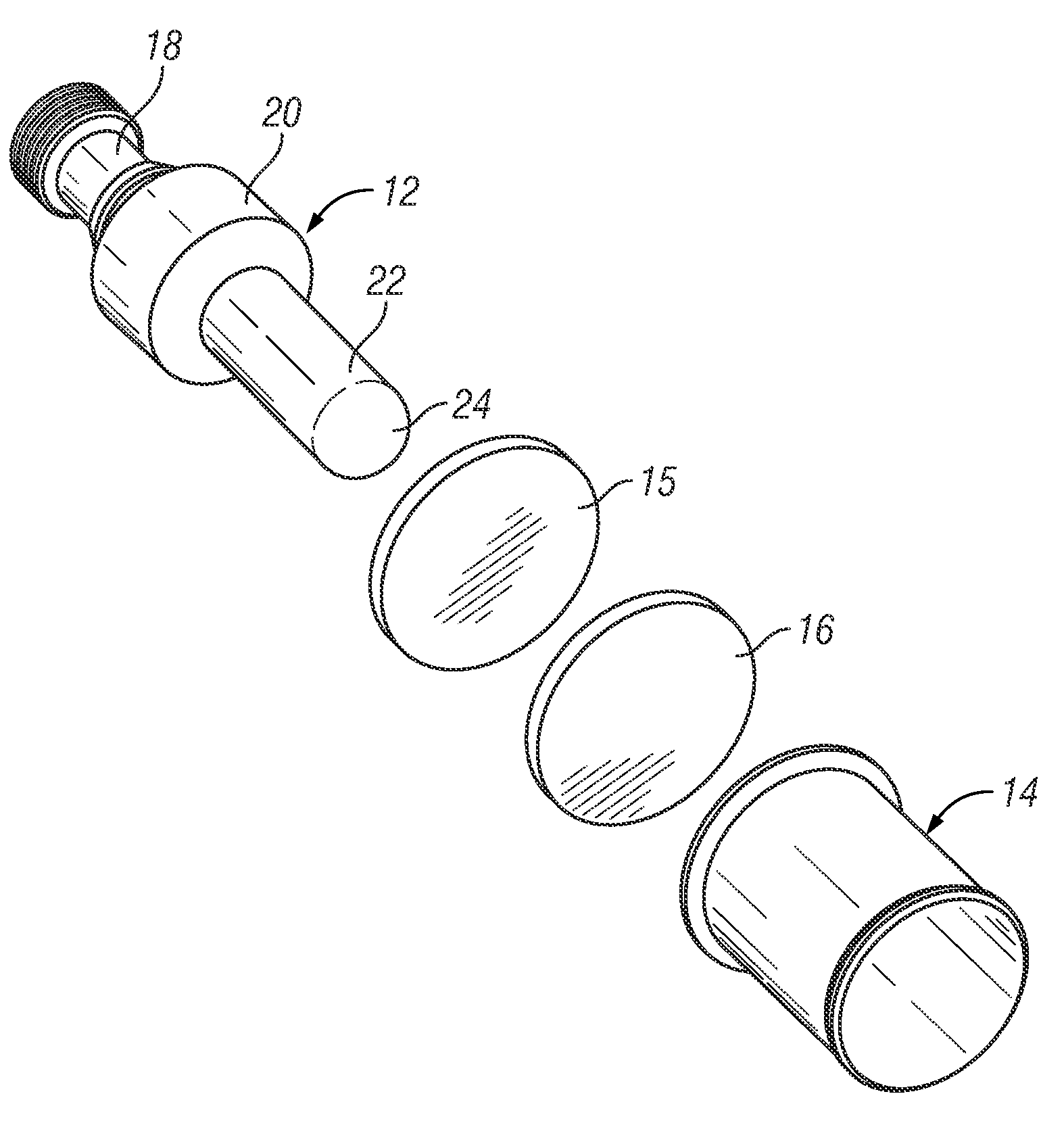
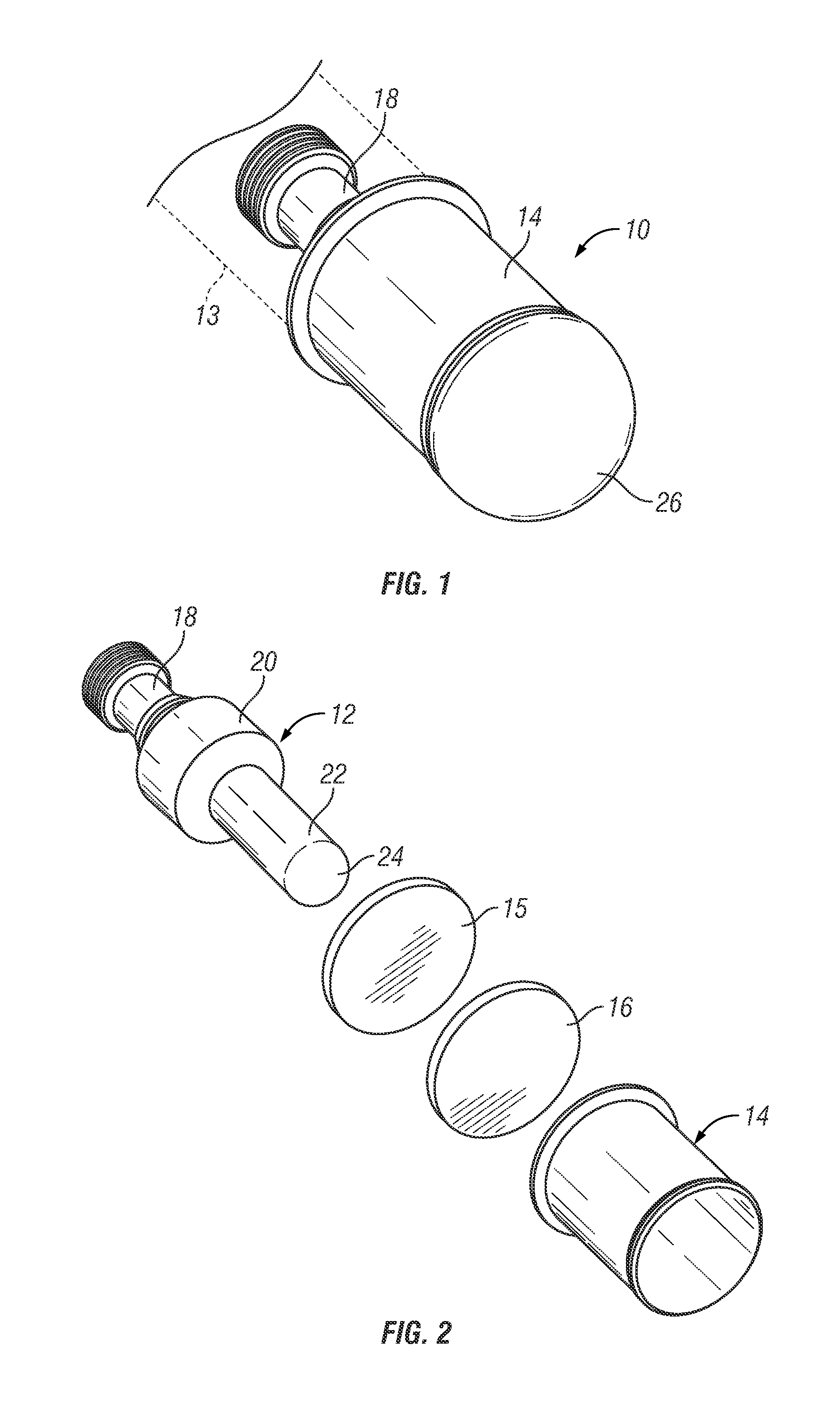
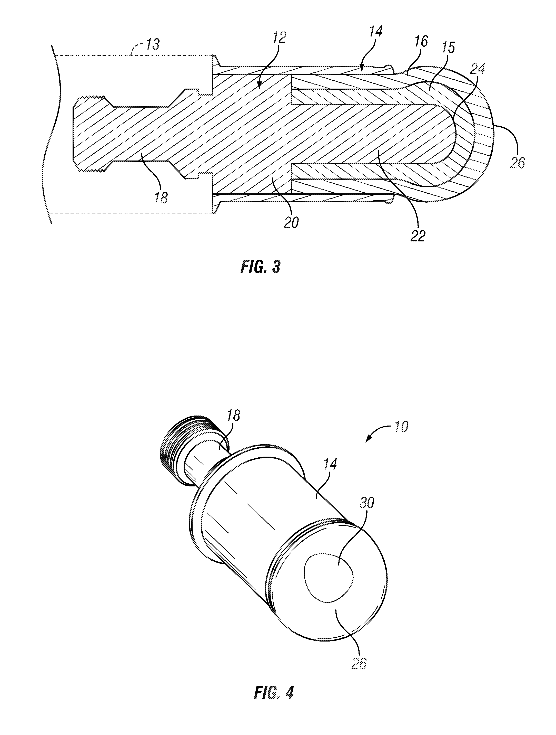
[0007]In one embodiment, a writing or drawing tip device for attachment to a touch screen stylus or handle has a rigid body of conductive material with a forward end portion or post which has a generally rounded tip, at least one layer of compressible material extending over the tip, and a retaining device or sleeve which secures the compressible layer to the body at a location to the rear of the rounded tip whereby the compressible material layer is trapped between the retaining sleeve and the body of the stylus to the rear of the tip but is not physically adhered to the tip itself. The tip can easily be applied to a touch screen with sufficient pressure to develop a contact patch between the compressible material layer and screen which is large enough to trigger an input on the screen, with the amount of pressure or applied force determining the size of the contact patch and providing tactile feedback to the user when writing or drawing on the screen.

Problems solved by technology

A stylus is generally required for writing or drawing on such panels, but existing devices are not sufficiently accurate for technical drawing, and also do not provide good feel or feedback for writing or drawing.
Touching the surface of the screen with a finger or with a conductive stylus results in a distortion of the screen's electrostatic field, and the resultant change in capacitance is detected as an input by the controller.
Although this device can be helpful for entering commands or navigating through menus, it is not accurate enough for drawing or writing purposes, due to the lack of feedback through the device.
Such devices are not capable of drawing accurate lines and do not give a good tactile feel or feedback for drawing or writing purposes.
There is also a risk of scratching the screen if too much pressure is applied so that the foam disc is completely compressed.

Method used


Image

  • Stylus tip device for touch screen
  • Stylus tip device for touch screen
  • Stylus tip device for touch screen

Examples


Embodiment Construction

[0017]Certain embodiments as disclosed herein provide for a stylus tip device for a touch screen such as a capacitative touch screen of a cell phones, personal digital assistants, video games, computers, and the like.

[0018]After reading this description it will become apparent to one skilled in the art how to implement the invention in various alternative embodiments and alternative applications. However, although various embodiments of the present invention will be described herein, it is understood that these embodiments are presented by way of example only, and not limitation. As such, this detailed description of various alternative embodiments should not be construed to limit the scope or breadth of the present invention.

[0019]FIGS. 1 to 4 illustrate a first embodiment of a stylus tip device 10 which is attached to a conductive pen or pencil-like body 13 to provide a touch screen stylus. A conventional touch screen handle or pen-like body 13 has a threaded bore or the like at o...


PUM


Abstract

A writing or drawing tip device for attachment to a touch screen stylus or handle has a rigid body of conductive material with a forward end mandrel having a rounded or elliptical tip, at least one layer of compressible material extending over the tip to produce a deformable rounded tip, and a retaining device which secures the compressible layer to the body at a location to the rear of the rounded tip. The deformable tip is applied to a touch screen to develop a contact patch between the compressible material layer and screen sufficient to trigger an input on the screen, with the amount of force applied to the tip determining the size of the contact patch.

Description

BACKGROUND[0001]1. Field of the Invention[0002]The present invention generally relates to a stylus or pen-like device used to input commands, hand written text or drawings on a touch screen of devices such as cell phones, personal digital assistants, video games, computers, and the like, and is particularly concerned with a tip for a touch screen stylus.[0003]2. Related Art[0004]Touch screen panels detect touching of the screen surface by a user's finger or a stylus to enable entry of commands. A stylus is generally required for writing or drawing on such panels, but existing devices are not sufficiently accurate for technical drawing, and also do not provide good feel or feedback for writing or drawing. There are several types of touch screen device, including resistive and capacitative touch screens. Resistive touch screens have two metal layers separated by a narrow gap. Touching the screen with a finger or writing instrument causes the layers to come into contact at the point wh...

Claims


Application Information

Patent Timeline
IPC IPC(8): G06F3/033G06F3/041
CPCG06F3/041G06F3/03545G06F3/0393G06F3/039
Inventor DUNAGAN, KELLY ALLAN
Owner DUNAGAN KELLY ALLAN
Why Eureka
Eureka Blog
Learn More