Ultrasound imaging device, signal processing device, and signal processing method
a signal processing and ultrasound imaging technology, applied in the field of ultrasound imaging devices, can solve the problems of large amount of calculation and inability to evaluate the degree of focus in pixels, and achieve the effect of high-quality ultrasound images
- Summary
- Abstract
- Description
- Claims
- Application Information
AI Technical Summary
Benefits of technology
Problems solved by technology
Method used
Image

Examples
first embodiment
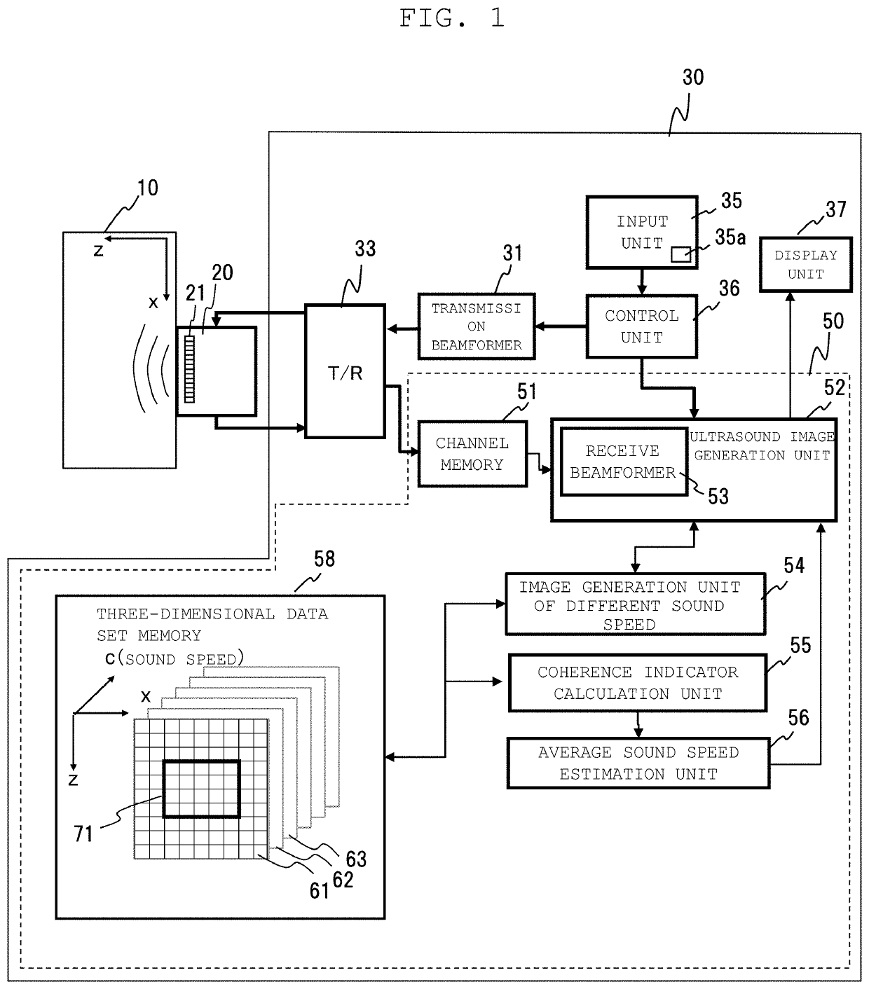
[0032]Hereinafter, an ultrasound imaging device according to a first embodiment will be described. FIG. 1 is a block diagram showing an overall configuration of the ultrasound imaging device according to the present embodiment.
[0033]In the first embodiment, after calculating coherence indicators for pixels, an average sound speed of an imaging target is estimated, and subsequent receive beamforming is performed using the estimated average sound speed.
[0034]As shown in FIG. 1, an ultrasound imaging device 30 according to the present embodiment includes a transmission beamformer 31, a transmit and receive switching unit (T / R) 33, a signal processing device 50, an input unit 35, a control unit 36, and a display unit 37. The ultrasound imaging device 30 is connected to a probe 20. A row (array) of ultrasound probe elements 21 is provided in the probe 20.
[0035]The signal processing device 50 includes, as a configuration for generating an ultrasound image, a channel memory 32 and an ultra...
second embodiment
[0073]An ultrasound imaging device according to a second embodiment will be described. FIG. 7 is a block diagram showing an overall configuration of the ultrasound imaging device according to the present embodiment. FIG. 8 is a diagram showing processing of the average sound speed estimation unit 56 according to the present embodiment. FIG. 9 is a flowchart showing operations of the ultrasound imaging device according to the present embodiment.
[0074]The ultrasound imaging device according to the second embodiment has the same configuration and operations as those of the ultrasound imaging device according to the first embodiment, but differs from the ultrasound imaging device according to the first embodiment in that a calculation unit of the sound speed that gives the maximum signal intensity 57 is further provided as shown in FIG. 7, and in the processing when the average sound speed estimation unit 56 estimates the average sound speed which is the optimal sound speed for beamform...
third embodiment
[0083]An ultrasound imaging device according to a third embodiment will be described. FIG. 10 is a block diagram showing an overall configuration of the ultrasound imaging device according to the present embodiment. FIG. 11 is a diagram showing processing of an image processing unit 59 according to the present embodiment. FIG. 12 is a flowchart showing operations of the ultrasound imaging device according to the present embodiment.
[0084]In the third embodiment, a high-quality image with reduced noise and artifacts is generated by weighting an image using coherence for each pixel.
[0085]The ultrasound imaging device according to the third embodiment has the same configuration and operations as those of the ultrasound imaging device according to the first embodiment, but is different from the first embodiment in that instead of the average sound speed estimation unit 56, the image processing unit 59 is provided as shown in FIG. 10. Hereinafter, the differences will be mainly described....
PUM
 Abstract
Description
Claims
Application Information
 - R&D
- Intellectual Property
- Life Sciences
- Materials
- Tech Scout
- Unparalleled Data Quality
- Higher Quality Content
- 60% Fewer Hallucinations
Browse by: Latest US Patents, China's latest patents, Technical Efficacy Thesaurus, Application Domain, Technology Topic, Popular Technical Reports.
© 2025 PatSnap. All rights reserved.Legal|Privacy policy|Modern Slavery Act Transparency Statement|Sitemap|About US| Contact US: help@patsnap.com