Ultrasound diagnostic apparatus

Inactive Publication Date: 2012-10-11
FUJIFILM CORP
View PDF8 Cites 4 Cited by
  • Summary
  • Abstract
  • Description
  • Claims
  • Application Information

AI Technical Summary

Benefits of technology

[0020]According to the invention, the reception amplifier having the amplifier amplifying the reception signal output from the transducer array and the selection unit switching the current value of the bias current supplied to the amplifier are arranged in the ultrasound probe, and the selection switch performing the switching operation to switch the current value by the selection unit is provided in the ultrasound probe. Therefore, it is possible to obtain a high-quality ultrasound image while suppressing the amount of heat generated in the ultrasound probe.

Problems solved by technology

In the apparatus described in JP 2005-253776 A which changes the actuation conditions of the transducer array at the time of transmission, it is difficult to handle heat generated at the time of reception in the ultrasound probe which performs the above-described digital process.
In the apparatus described in JP 2009-148424 A which stops the operation of the reception circuit in the probe for a predetermined period, such as a freeze period, a blanking period, a period in which movement of the probe is equal to or smaller than a prescribed value, or a period in which the temperature of the probe is equal to or higher than a prescribed value, while it is possible to reduce heat generated at the time of reception in the ultrasound probe which performs a digital process, the ratio of the predetermined period is generally small compared to the operation time, making it difficult to sufficiently reduce heat generated in the ultrasound probe.

Method used


Image

  • Ultrasound diagnostic apparatus
  • Ultrasound diagnostic apparatus
  • Ultrasound diagnostic apparatus

Examples


Embodiment Construction

[0026]Hereinafter, an ultrasound diagnostic apparatus of the invention will be described in detail in connection with a preferred embodiment illustrated in the accompanying drawings.

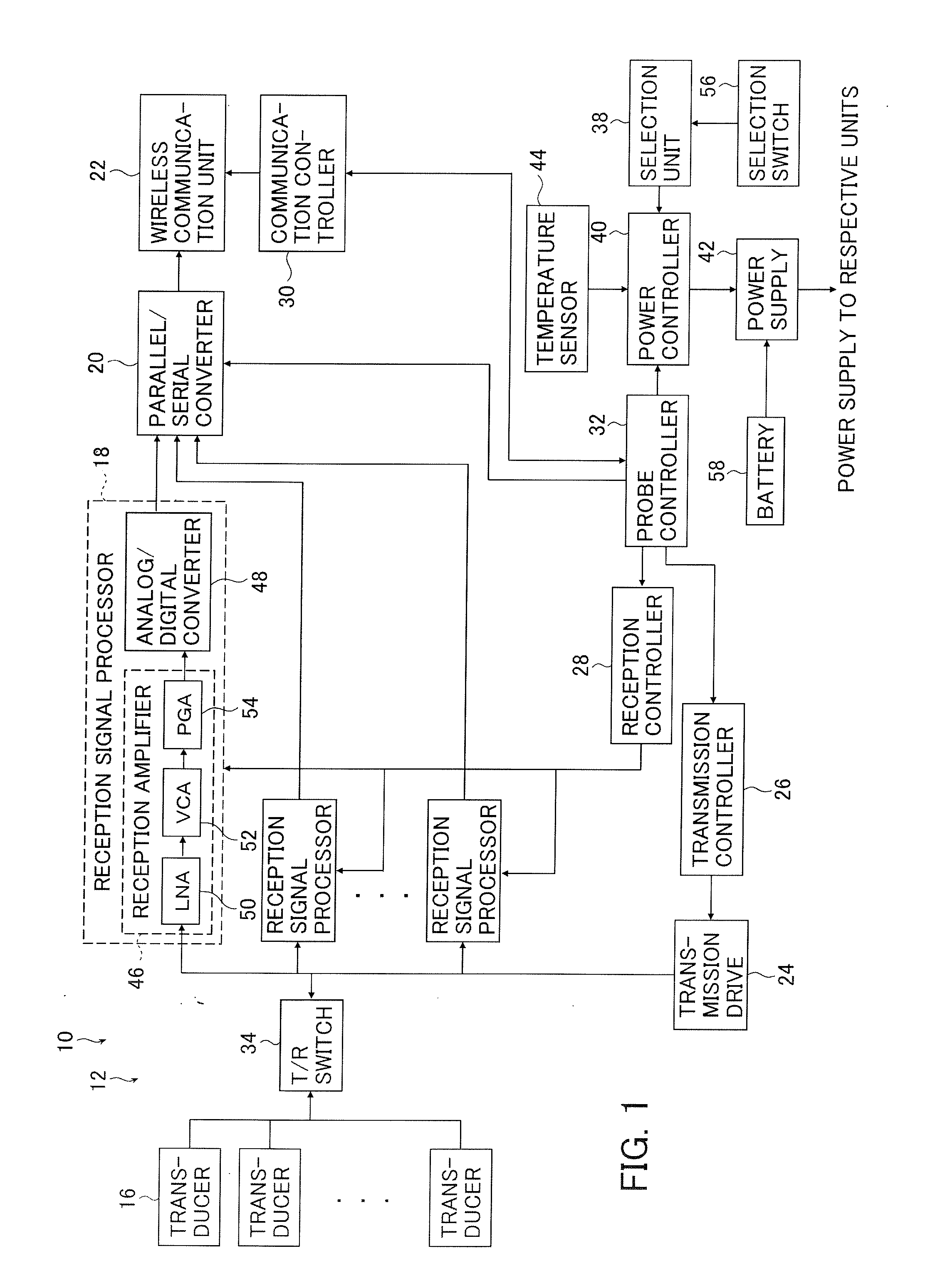
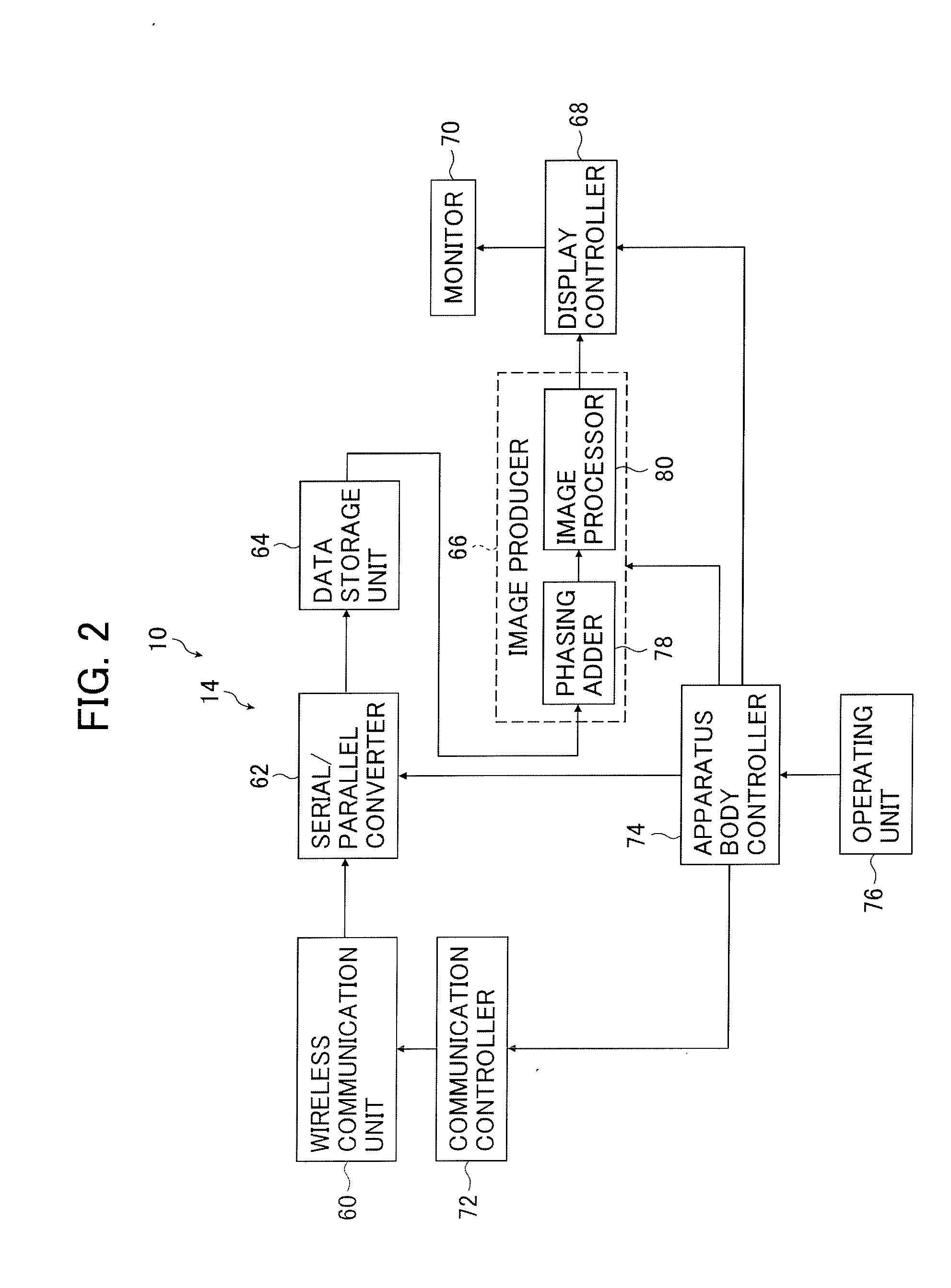
[0027]FIG. 1 is a block diagram conceptually illustrating the configuration of an ultrasound probe in an ultrasound diagnostic apparatus of the invention. FIG. 2 is a block diagram conceptually illustrating the configuration of a diagnostic apparatus body in the ultrasound diagnostic apparatus of the invention.

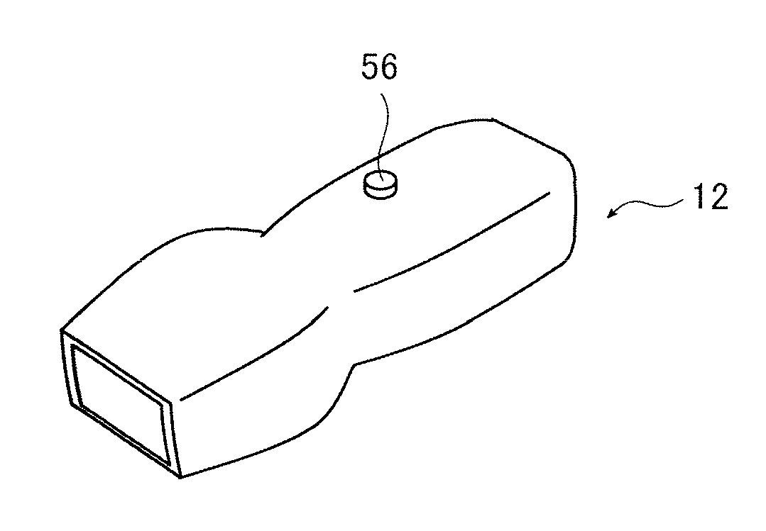
[0028]An ultrasound diagnostic apparatus 10 includes an ultrasound probe 12, and a diagnostic apparatus body 14 which is connected to the ultrasound probe 12 through wireless communication.

[0029]The ultrasound probe 12 has a plurality of ultrasound transducers 16 which form a plurality of channels of a one or two-dimensional transducer array. Reception signal processors 18 are connected to the respective transducers 16 through a T / R switch 34, and a wireless communication unit 22 is connected to th...


PUM


Abstract

An ultrasound diagnostic apparatus comprises: an ultrasound probe, the ultrasound probe having a transducer array which transmits ultrasonic waves, receives an ultrasonic echo reflected by a subject, and outputs a reception signal according to the received ultrasonic waves, a signal processor which includes a reception amplifier having an amplifier amplifying the reception signal output from the transducer array and processes the reception signal, a selection unit for switching a current value of a bias current supplied to the amplifier, and a selection switch which performs a switching operation to switch the current value by the selection unit; and a diagnostic apparatus body which produces an ultrasound image according to the reception signal processed by the signal processor of the ultrasound probe.

Description

BACKGROUND OF THE INVENTION[0001]The present invention relates to an ultrasound diagnostic apparatus, and in particular, to a technique for suppressing the amount of heat generated in an ultrasound probe of an ultrasound diagnostic apparatus, which performs diagnosis on the basis of an ultrasound image produced through transmission and reception of ultrasonic waves from a transducer array in the ultrasound probe.[0002]An ultrasound diagnostic apparatus using an ultrasound image has hitherto been put into practical use in the field of medicine. In general, this type of ultrasound diagnostic apparatus has an ultrasound probe equipped with a transducer array and an apparatus body connected to the ultrasound probe. Ultrasonic waves are transmitted from the ultrasound probe toward a subject, an ultrasonic echo from the subject is received by the ultrasound probe, and the reception signal is electrically processed by the apparatus body to produce an ultrasound image.[0003]In this ultrasou...

Claims


Application Information

Patent Timeline
IPC IPC(8): A61B8/14
CPCA61B8/14A61B8/56A61B8/546A61B8/4472
Inventor TAKAHASHI, YASUFUMI
Owner FUJIFILM CORP
Why Eureka
Try Eureka