Ultrasound diagnostic apparatus and operation method of ultrasound diagnostic apparatus

a diagnostic apparatus and ultrasound technology, applied in the direction of instruments, catheters, mechanical vibration separation, etc., can solve the problems of increasing cost, circuit size, and difficulty in mounting the above-mentioned devices in the existing system, so as to reduce the frame rate, reduce the image quality of the ultrasound image, and avoid the effect of increasing the cos

Active Publication Date: 2020-01-02
FUJIFILM CORP
View PDF15 Cites 2 Cited by
  • Summary
  • Abstract
  • Description
  • Claims
  • Application Information

AI Technical Summary

Benefits of technology

[0027]In the invention, the polarization processing is performed using the existing pulse generation circuit. In the ultrasound diagnostic apparatus, the second transmission signal in the case of performing polarization processing is a pulse wave, and the pulse generation circuit does not need to output a DC waveform. Therefore, it is possible to perform the polarization processing without significantly changing the existing circuit and accordingly without increasing the cost.
[0028]In addition, since the polarization processing is performed during the non-diagnosis period, the frame rate is not reduced. Therefore, without reducing the image quality of the ultrasound image, the reception sensitivities of the plurality of ultrasound transducers can always be kept satisfactory. As a result, a high-quality ultrasound image can always be acquired.

Problems solved by technology

Accordingly, it is very difficult to mount those described above in the existing system.
Therefore, since the pulse wave and the DC waveform are output in the same circuit, the circuit size becomes large.
This may cause an increase in cost.

Method used


Image

  • Ultrasound diagnostic apparatus and operation method of ultrasound diagnostic apparatus
  • Ultrasound diagnostic apparatus and operation method of ultrasound diagnostic apparatus
  • Ultrasound diagnostic apparatus and operation method of ultrasound diagnostic apparatus

Examples


Embodiment Construction

[0049]An ultrasound diagnostic apparatus according to an embodiment (the present embodiment) of the invention will be described in detail below with reference to preferred embodiments shown in the accompanying diagrams.

[0050]The present embodiment is a representative embodiment of the invention, but is merely an example and does not limit the invention.

[0051]In addition, in this specification, the numerical range expressed by using “˜” means a range including numerical values described before and after “˜” as a lower limit and an upper limit.

[0052]>

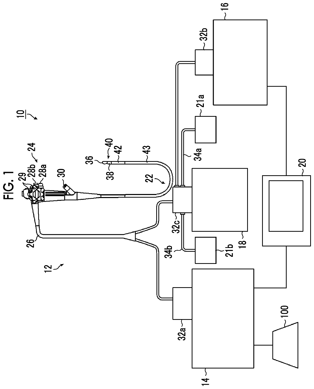
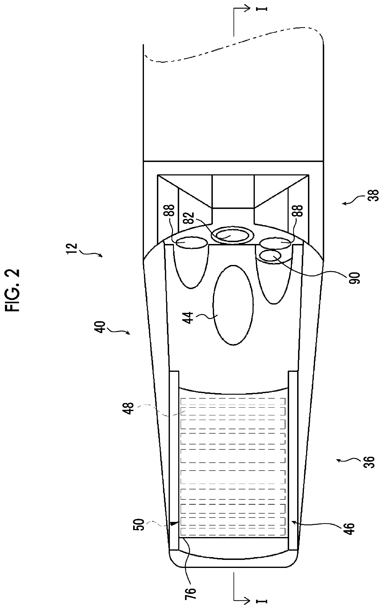
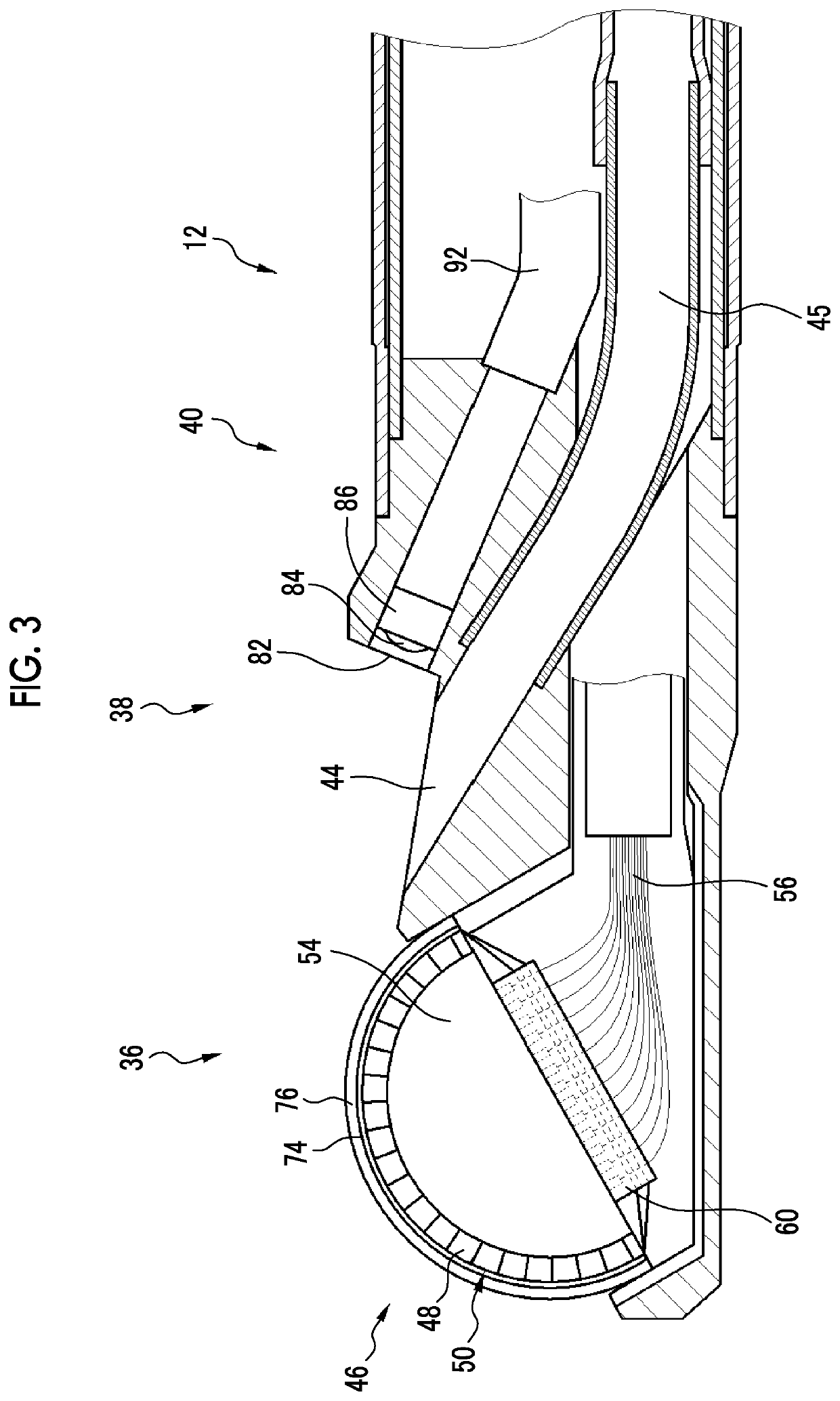
[0053]The outline of an ultrasound diagnostic apparatus 10 according to the present embodiment will be described with reference to FIG. 1. FIG. 1 is a diagram showing the schematic configuration of ultrasound diagnostic apparatus 10.

[0054]The ultrasound diagnostic apparatus10 is used to observe (hereinafter, also referred to as ultrasound diagnosis) the state of an observation target part in a body of a patient, who is a subject, using ul...


PUM


Abstract

In an ultrasound diagnostic apparatus and an operation method of the ultrasound diagnostic apparatus of the invention, a control circuit performs polarization processing on a plurality of ultrasound transducers in a non-diagnosis period, during which transmission of ultrasound waves and reception of reflected waves for performing ultrasound diagnosis are not performed, in a case where the cumulative driving time of the plurality of ultrasound transducers for performing the ultrasound diagnosis becomes equal to or longer than a specified time. A transmission circuit generates a first transmission signal having a driving voltage for performing ultrasound diagnosis using a pulse generation circuit in the case of performing the ultrasound diagnosis, and generates a second transmission signal having a polarization voltage for performing polarization processing using the same pulse generation circuit as in the case of generating the first transmission signal in the case of performing the polarization processing.

Description

CROSS-REFERENCE TO RELATED APPLICATIONS[0001]The present application claims priority under 35 U.S.C. § 119 to Japanese Patent Application No. 2018-124170, filed on Jun. 29, 2018. Each of the above application(s) is hereby expressly incorporated by reference, in its entirety, into the present application.BACKGROUND OF THE INVENTION1. Field of the Invention[0002]The present invention relates to an ultrasound diagnostic apparatus, which performs polarization processing on a plurality of ultrasound transducers that an ultrasound endoscope comprises, and an operation method of an ultrasound diagnostic apparatus.2. Description of the Related Art[0003]An ultrasound diagnostic apparatus that acquires an ultrasound image of the inside of a subject by transmitting and receiving ultrasound waves by driving a plurality of ultrasound transducers inside the subject is already known. In the ultrasound diagnostic apparatus, the plurality of ultrasound transducers are, for example, single crystal tr...

Claims


Application Information

Patent Timeline
Patent Type & Authority Applications(United States)
IPC IPC(8): A61B8/00A61B8/12A61B8/08G01S7/53G01S15/89G01S15/02G01S7/56
CPCA61B8/5207A61B8/465G01S15/025A61B8/54A61B8/12G01S7/56G01S15/89A61B8/5261A61B8/4488A61B8/5292G01S7/53A61B8/463B06B1/0215A61B8/14A61B8/488A61B8/4416A61B8/5246A61B8/58G01S7/52098G01S7/52074G01S7/5202G01S15/86
Inventor YAMAMOTO, KATSUYAMORIMOTO, YASUHIKOOKADA, SATORU
Owner FUJIFILM CORP
Why Eureka
Try Eureka