Solar tracker with orientable solar panels arranged in rows

a solar tracker and orientable technology, applied in the field of solar trackers, can solve the problems of requiring a more complex transmission system, occupying more space, and affecting the operation of solar trackers

Active Publication Date: 2022-10-13
TRINA SOLAR S L U
View PDF2 Cites 0 Cited by
  • Summary
  • Abstract
  • Description
  • Claims
  • Application Information

AI Technical Summary

Problems solved by technology

Since it is an indirect drive of the axis, it requires a more complex transmission system and takes up more space.
However, the orographic variety of the terrains on which the solar trackers must be installed means that there are frequent height and / or lateral deviations between the photovoltaic modules making up the rows that form the solar tracker, which entails assembling difficulties that make the installations more expensive and hinder the operating activity of the solar tracker.
It also occurs in the known solutions that the drive means for driving the transmission bars are made up of at least one motor that is arranged perpendicular to the theoretical longitudinal axis of the transmission bar that it must activate or arranged parallel to said bar, both solutions taking up a lot of space and giving rise to accidents when moving under the solar panels.
Another problem lies in the drive means for driving the rotation axis which, in addition to being complex, which reduces the reliability of the system, are arranged flush with the ground with transmission elements up to the rotation axis.
This entails a two-fold problem: on the one hand, the arrangement of these drive means flush with the ground gives rise to humidity problems and even problems with flood water covering caused by heavy rains and, on the other hand, the existence of transmission elements from the flush level to the rotation axis poses a risk during the movement of the operators under the solar panels.

Method used


Image

  • Solar tracker with orientable solar panels arranged in rows
  • Solar tracker with orientable solar panels arranged in rows
  • Solar tracker with orientable solar panels arranged in rows

Examples


Embodiment Construction

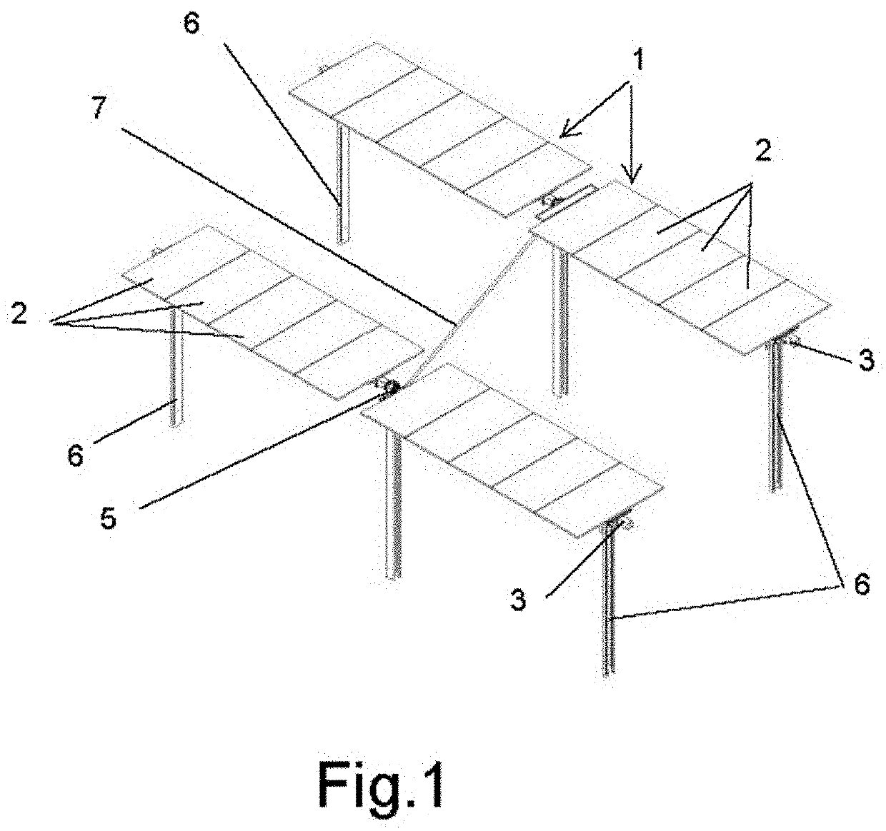
[0033]The object of the invention relates to a solar tracker formed by at least two rows of photovoltaic modules (1), each of which is made up of a series of solar panels (2) mounted on respective frames. The solar panels (2) of each photovoltaic module (1) are mounted on a horizontal rotation axis (3) that is oriented in the north-south direction, such that the rotation thereof is adjusted so that the normal plane to the surface of the solar panels (2) coincides at all times with the local meridian containing the sun.

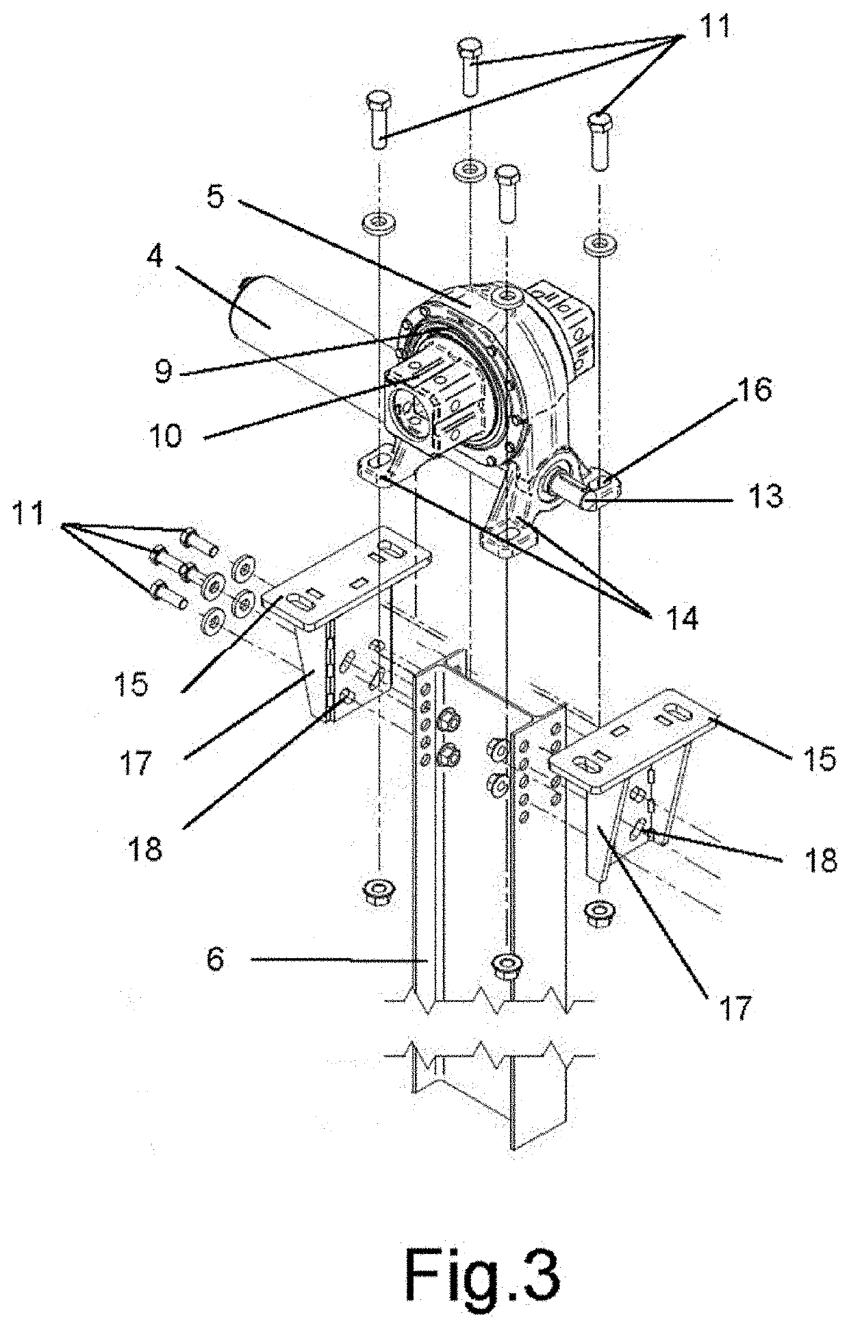
[0034]In connection with the rotation axes (3) of a row of photovoltaic modules (1), at least one motor (4) is arranged, the driving of which results in the rotation of the horizontal rotation axis (3) associated therewith.

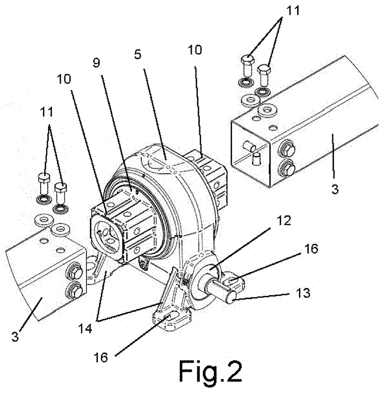
[0035]In each of the rows of photovoltaic modules (1) the different rotation axes (3) are associated with each other by means of rotation transmission modules (5), which are arranged on support pillars (6) for supporting the photovoltaic modules (1) ...


PUM


Abstract

A solar tracker with orientable solar panels arranged in rows, having at least two rows of photovoltaic modules (1) carrying the solar panels (2), arranged on pillars (6), the solar panels (2) mounted on respective rotation axes (3) longitudinally associated with each other by rotation transmission (5), driven by at least one motor (4) establishing the movement of all the solar panels (2) from a single actuation point, the rows of photovoltaic modules (1) related to each other by at least one transmission bar (7), joined by universal joints (8), to respective rotation transmission (5), the drive motor (4) is coupled in longitudinal alignment with respect to a transverse transmission (12) that meshes with a rotation transmission (5) and with respect to which the universal joint (8) of one end of the corresponding transmission bar (7) is joined in longitudinal alignment on the other side.

Description

CROSS REFERENCE TO RELATED APPLICATION[0001]This application claims the benefit of priority of Spanish Patent Application No. 0202100700, filed on Apr. 7, 2021, the content of which is incorporated herein by reference.TECHNICAL FIELD[0002]The present invention relates to solar trackers made up of photovoltaic modules formed by frames on which solar panels are mounted, these photovoltaic modules being arranged in rows with a drive for orienting towards the position of the sun, proposing a solar tracker of this type developed with structural assembly features that improve the operational functionality and the adaptability of installation on terrains of any orography.STATE OF THE ART[0003]In the industry of energy production by harnessing the sun's energy, solar trackers formed by photovoltaic modules that are made up of frames on which solar panels that can be oriented towards the position of the sun are mounted are well known. There is a version of these solar trackers made up of pho...

Claims


Application Information

Patent Timeline
Patent Type & Authority Applications(United States)
IPC IPC(8): H02S20/32
CPCH02S20/32Y02E10/47H02S20/10F24S30/425F24S2030/136F24S2025/019F24S2030/12F24S2030/15Y02E10/50
Inventor DUAN, SHUNWEYQUAN, PENGGOMEZ GARCIA, JUAN MANUEL
Owner TRINA SOLAR S L U
Why Eureka
Try Eureka