
Hybrid transmission device

Pending Publication Date: 2022-10-13
MAGNA PT B V & CO KG
View PDF0 Cites 0 Cited by
  • Summary
  • Abstract
  • Description
  • Claims
  • Application Information

AI Technical Summary

Benefits of technology

The invention is aims to improve a hybrid transmission device by making it lighter, space-saving, and less expensive. The device can be mounted using a single bearing or both bearings, which helps to save on costs and optimize space. By eliminating end shields and minimizing the tilting of the pinion under load, the device can also be more efficient and quieter. The invention also provides a method for assembling the device, which makes it easier to mount and modify. Overall, the technical effects of the invention are improved efficiency, space-saving, and cost savings.

Problems solved by technology

This results in an additional structural space requirement in a radial and axial direction of the electric machine module.
Also, owing to the overhung mounting, a greater degree of tilting of the pinion occurs during operation under load than would be the case if said bearing were arranged “behind the pinion”.
This tilting results in undesired acoustic conspicuities (NVH—noise, vibration and harshness).
The end shields, and likewise the relatively large bearing, also entail high costs.

Method used


Image

  • Hybrid transmission device
  • Hybrid transmission device
  • Hybrid transmission device

Examples


Embodiment Construction

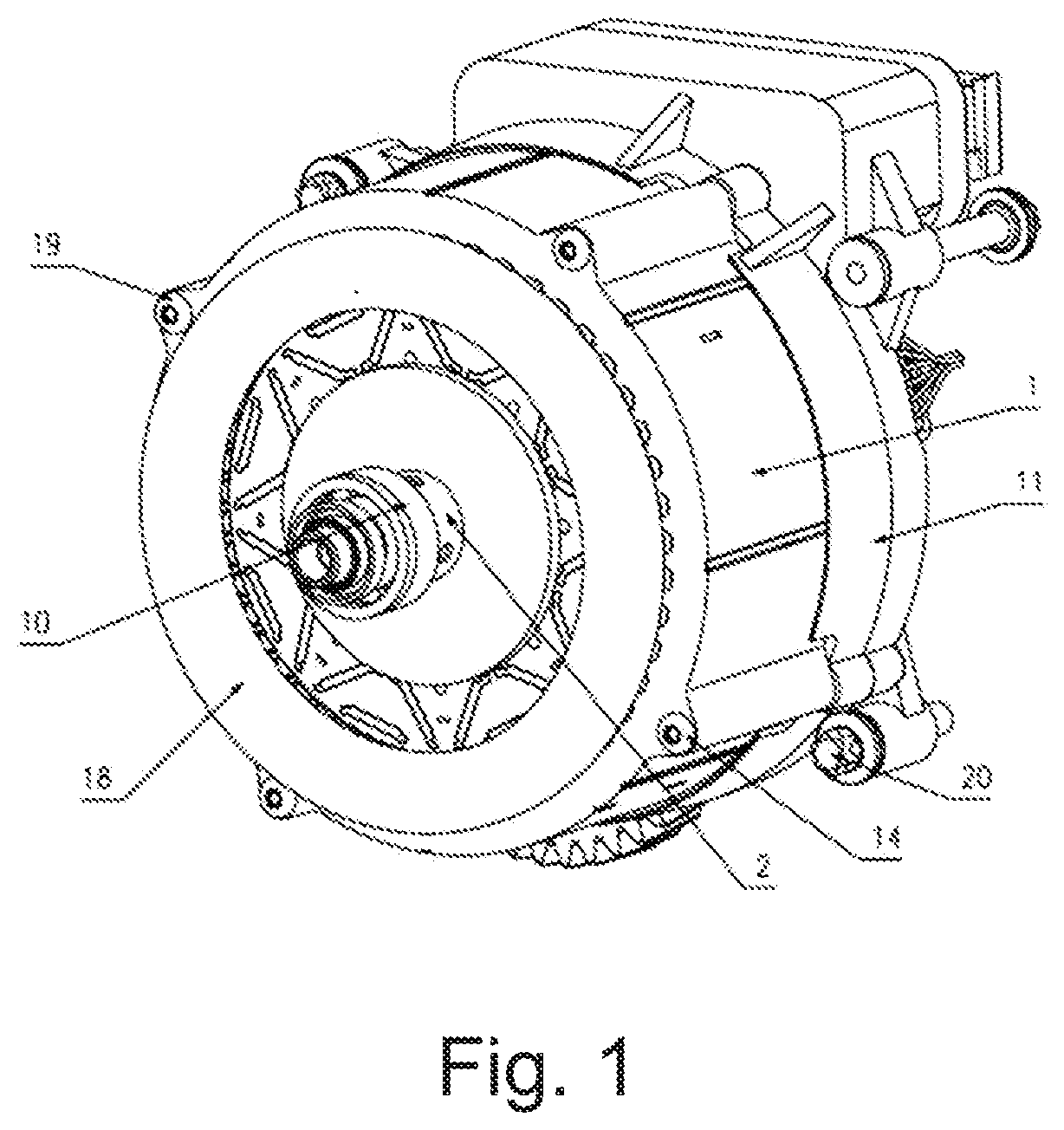
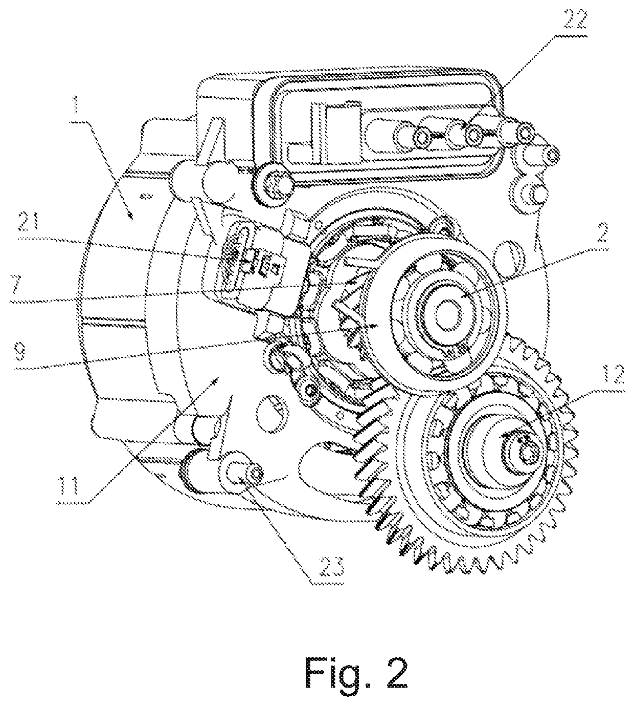
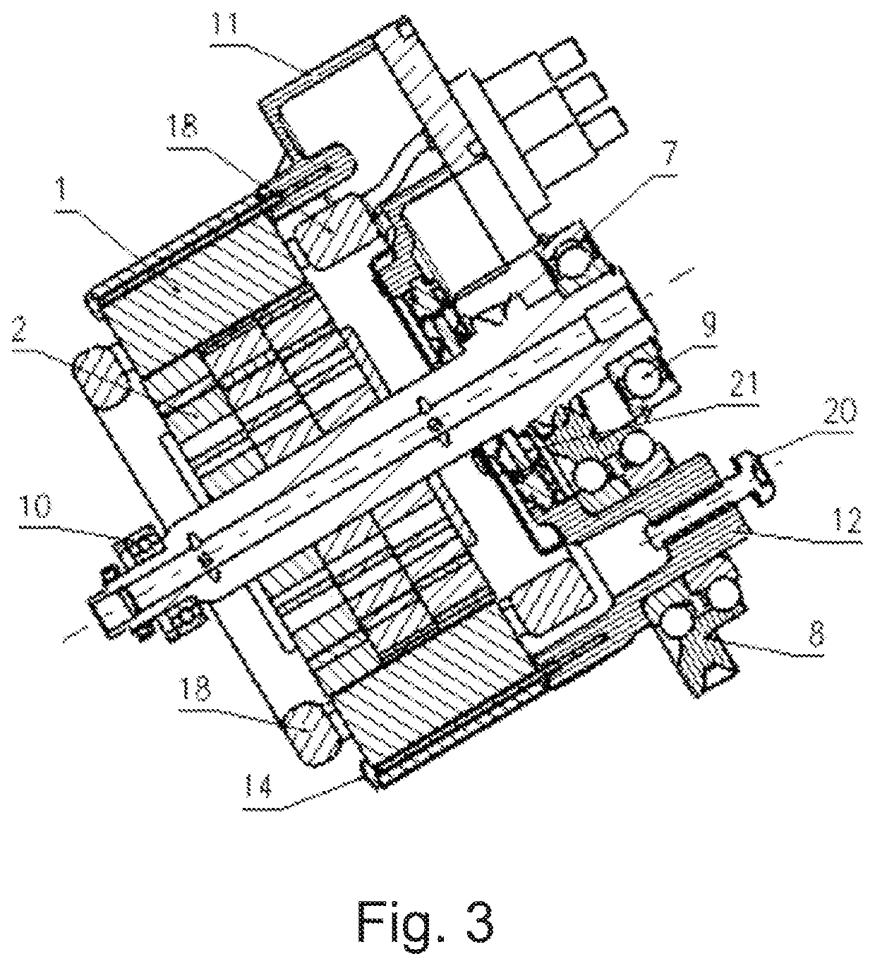
[0036]FIGS. 1-3 illustrate an electric machine of a hybrid transmission device according to the invention—in FIG. 1 as viewed from the side of the second bearing 10, in FIG. 2 as viewed from the side of the first bearing 9, and in FIG. 3 in a section from a side elevation.

[0037]The electric machine comprises an externally situated stator 1 and an internally situated rotatable rotor shaft 2. A hybrid transmission device having an electric machine of said type (see FIG. 4) comprises a transmission 3 in a transmission housing 4 and a clutch 5 in a clutch housing 6. The stator 1 is then fastened in the transmission housing 4.

[0038]The electric machine and the transmission 3 are arranged in a P2.5 architecture.

[0039]The rotor shaft 2 has, at a first end, a pinion 7 (FIGS. 2 and 3) that meshes with an intermediate gear 8 of the transmission 3 (FIG. 4 and FIG. 3). The rotor shaft 2 is mounted by means of a first and a second bearing 9, 10 in the region of the first end and in the region of...


PUM


Abstract

A hybrid transmission device, comprising an electric machine, wherein the electric machine has an externally situated stator and an internally situated rotor shaft, wherein the hybrid transmission device furthermore comprises a transmission in a transmission housing and a clutch in a clutch housing, wherein the stator is fastened in the transmission housing, wherein the rotor shaft has, at a first end, a pinion that meshes with an intermediate gear of the transmission, wherein the rotor shaft is mounted in the region of the first end and in the region of the oppositely situated second end of the rotor shaft by means of a first and a second bearing, wherein an intermediate plate fastened to the stator is arranged axially in the region of the first end of the rotor shaft, wherein the second bearing for the mounting of the second end of the rotor shaft is fixed directly in the clutch housing, and the first bearing for the mounting of the first end of the rotor shaft is fixed to the transmission housing or is fixed to the intermediate plate, and a method for assembling a hybrid transmission device of said type.

Description

CROSS-REFERENCE TO RELATED APPLICATIONS[0001]This application claims priority to German Application No. DE 102021203495.0, filed on Apr. 8, 2021 at the German Patent Office and which is hereby incorporated by reference in its entirety.FIELD OF THE INVENTION[0002]The present invention relates to a hybrid transmission device comprising an electric machine and a transmission, and further relates to a method for assembling such a hybrid transmission device.BACKGROUND OF THE INVENTION[0003]This section provides information related to the present disclosure which is not necessarily prior art[0004]Hybrid electric vehicles, also referred to as hybrid vehicles, are nowadays well-known and use at least one electric machine and an additional drive, commonly an internal combustion engine, for the propulsion of the vehicle. In the case of a parallel hybrid drive, the electric motor and the internal combustion engine can impart their drive torques to the drivetrain simultaneously. Different archi...

Claims


Application Information

Patent Timeline
IPC IPC(8): H02K15/02H02K1/28H02K3/12H02K3/28H02K7/00H02K7/08H02K7/116
CPCH02K15/028H02K1/28H02K3/12H02K3/28H02K7/003H02K7/083H02K7/116B60K6/26B60K6/38B60K6/36B60K6/40H02K7/10H02K7/1163H02K15/14H02K15/00H02K7/085F16H2057/02034F16H2057/0216F16H2057/005F16H2057/0056F16H57/023H02K7/108F16H57/021B60K6/405Y02T10/62B60K2006/4816B60K6/48B60K2006/4825
Inventor VIEBACH, RICHARDPRUY, MATTHIAS
Owner MAGNA PT B V & CO KG
Learn More