
Catheter for aortic valvuloplasty

a technology for aortic valves and catheters, which is applied in the field of catheters for aortic valves, can solve the problems of inability to apply valve replacements in cases where long-term prognosis cannot be expected, and the prognosis after symptoms is extremely poor at 2 to 5 years, so as to increase the therapeutic

Pending Publication Date: 2022-10-13
OSAKA UNIV
View PDF0 Cites 0 Cited by
  • Summary
  • Abstract
  • Description
  • Claims
  • Application Information

AI Technical Summary

Benefits of technology

The present invention is a catheter for aortic valvuloplasty, which can improve treatment outcomes while being minimally invasive. This means that it can offer new treatment options for patients who cannot be treated by curative treatment.

Problems solved by technology

In aortic valve stenosis, which is a type of heart disease, symptoms such as fainting, chest pain, and shortness of breath appear, and the prognosis after the onset of symptoms is extremely poor at 2 to 5 years.
Though valve replacement has achieved good results as a curative treatment, the valve replacement is not applied in cases where long-term prognosis cannot be expected.

Method used


Image

  • Catheter for aortic valvuloplasty
  • Catheter for aortic valvuloplasty
  • Catheter for aortic valvuloplasty

Examples


first embodiment

1. First Embodiment

1-1. Configuration of Catheter 10

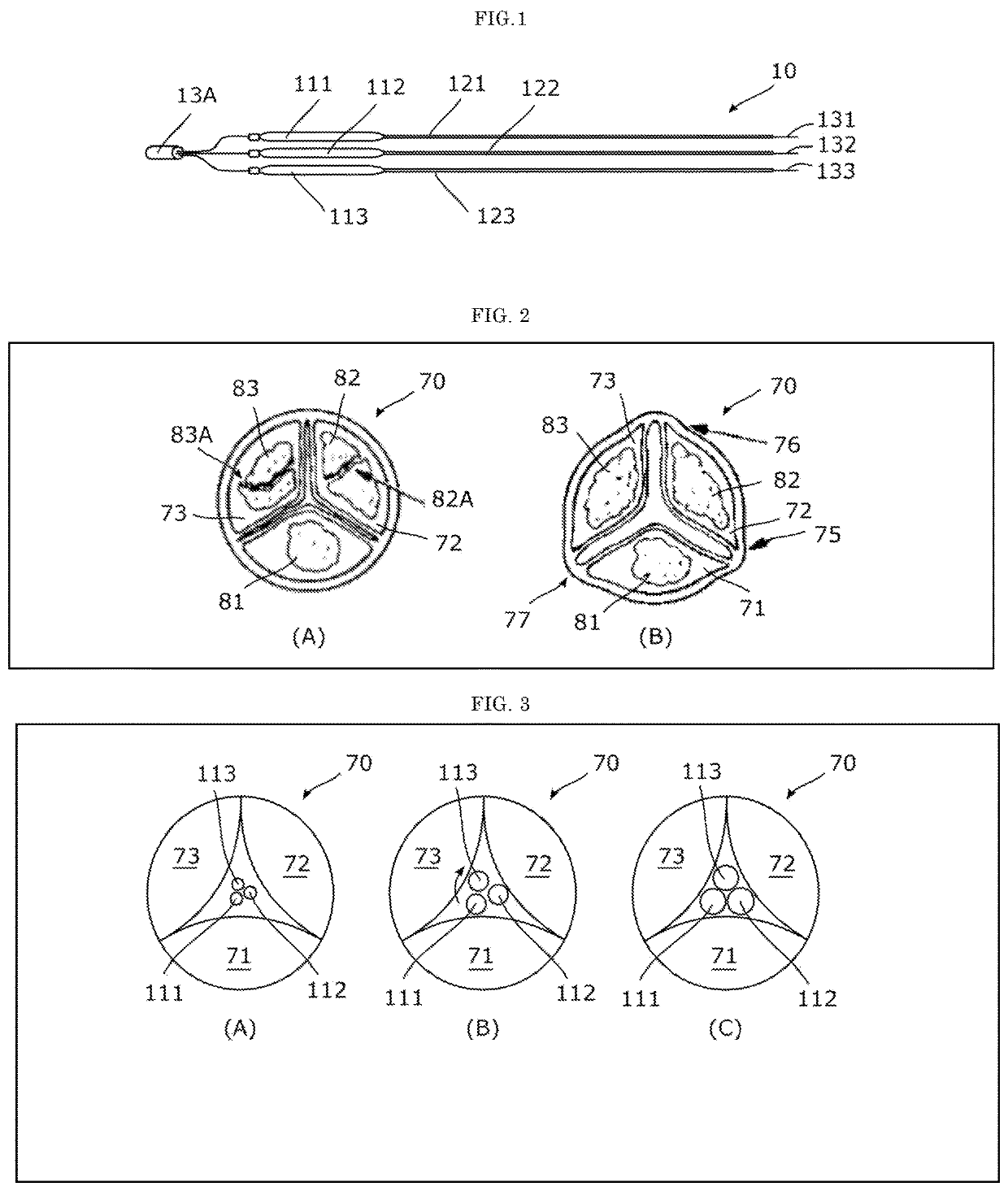
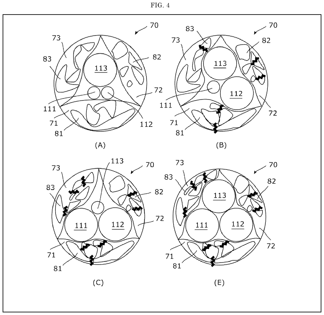
[0024]The catheter 10 in accordance with the first embodiment will be described. The catheter 10 is a medical device used for the plasty of the aortic valve 70. Here, the aortic valve 70 may be simply referred to as a valve 70 or a stenosis valve 70.

[0025]As shown in FIG. 1, the catheter 10 includes balloons 111-113, shafts 121-123 and wires 131-133. Here, the balloons 111-113 correspond to the first to third balloons and may be collectively referred to as the balloon 11. Further, the shafts 121-123 correspond to the first to third shafts and may be collectively referred to as the shaft 12. The wires 131-133 correspond to the first to third wires, and may be collectively referred to as wire 13.

[0026]The balloon 11 can be expanded and contracted by supplying a fluid (gas or liquid). The balloon 11 can change its relative positional relationship with other balloons by the operation of a medical doctor.

[0027]Considering the introducti...

second embodiment

2. Second Embodiment

2-1. As to the Catheter 20

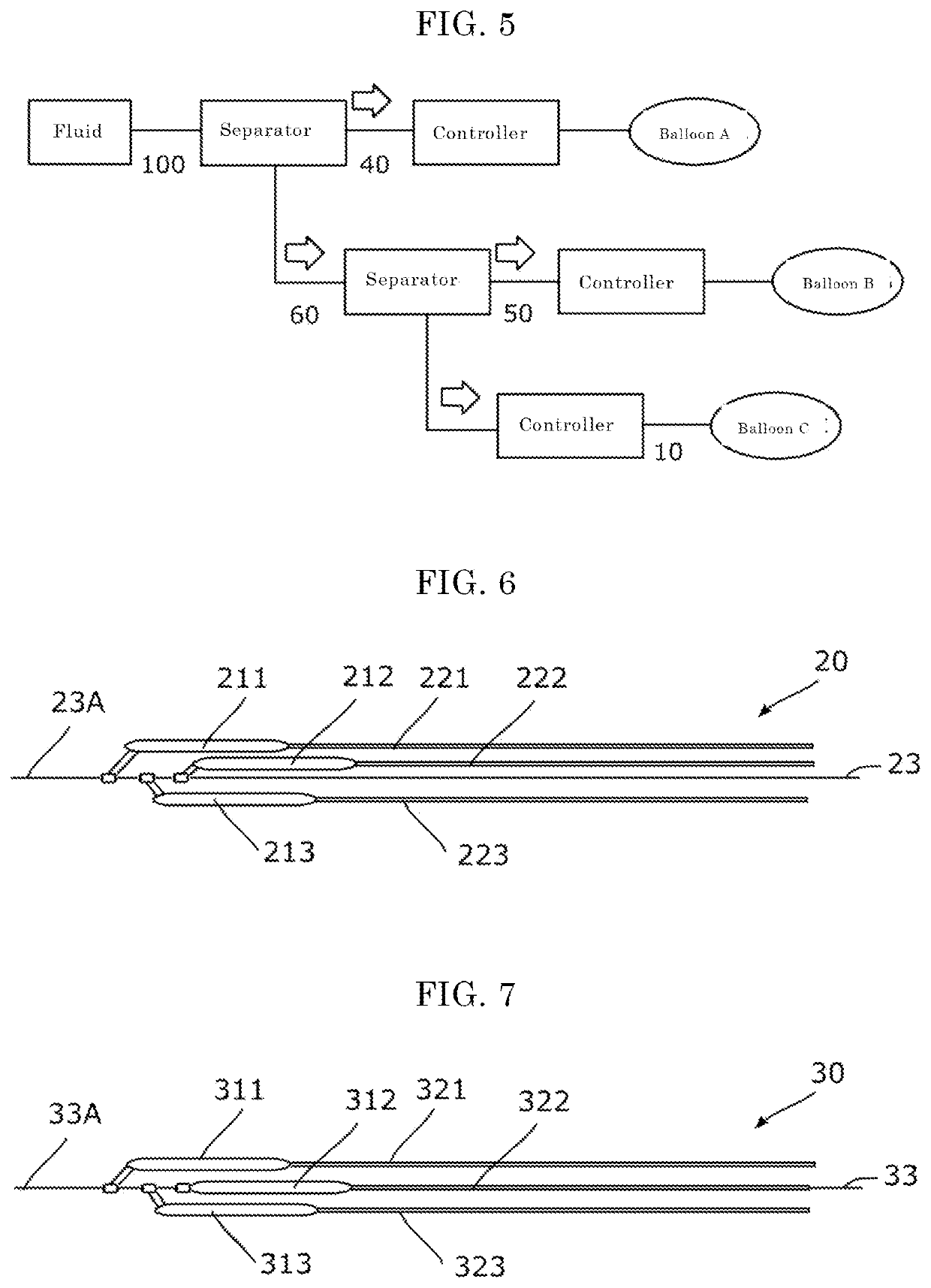
[0045]The catheter 20 in accordance with the second embodiment will be described with reference to FIG. 6.

[0046]As shown in the drawings, the catheter 20 includes the balloons 211-213, the shafts 221-223 and the wire 23. Here, the balloons 211-213 may be collectively referred to as balloon 21. Further, the shafts 221-223 may be collectively referred to as the shaft 22.

[0047]The size of the balloon 21 may be the same as the size of the balloon 11 in accordance with the first embodiment. Further, the size of the shaft 22 may be the same as the size of the shaft 12 in accordance with the first embodiment. The balloon 21 and the shaft 22 constitute a set of balloon catheter, and , as illustrated in FIG. 6, the balloon catheter is supported by the wire 23 at the tip (for example, about 1 cm). That is, in the second embodiment, a balloon catheter of the short monorail system is employed. Therefore, the balloon 21 and the shaft 22 are located o...


PUM


Abstract

To provide a catheter for aortic valvuloplasty in which it is possible to significantly increase the therapeutic effect despite being minimally invasive. The present invention provides a catheter for aortic valvuloplasty characterized by including: first to third balloons that can expand and contract due to supply of a fluid, it being possible to change the relative positional relationships of the first to third balloons; first to third shafts that connect to the first to third balloons at the tip and supply fluid to the first to third balloons to cause the first to third balloons to expand and contract independently of each other; and at least one wire that introduces the first to third balloons from outside the patient's body to the aortic valve.

Description

TECHNICAL FIELD[0001]The present invention relates to a catheter for aortic valvuloplasty.BACKGROUND ART[0002]In aortic valve stenosis, which is a type of heart disease, symptoms such as fainting, chest pain, and shortness of breath appear, and the prognosis after the onset of symptoms is extremely poor at 2 to 5 years. Though valve replacement has achieved good results as a curative treatment, the valve replacement is not applied in cases where long-term prognosis cannot be expected.[0003]As a treatment option for such cases, there is valvuloplasty using a balloon catheter. In this valvuloplasty, a catheter is inserted from the femoral artery in the inguinal region, a balloon is inflated inside the narrowed valve, and the valve is dehiscenced to release the stenosis (for example, Patent Literature 1).PRIOR ART REFERENCEPatent Reference[0004]Patent Reference 1: JP 2005-334384ASUMMARY OF THE INVENTIONProblem to be Solved by the Invention[0005]However, the aforementioned valvuloplasty...

Claims


Application Information

Patent Timeline
IPC IPC(8): A61M25/10A61M25/00
CPCA61M25/104A61M25/1011A61M25/0068A61M2025/09183A61M25/09A61M2025/1079A61M29/02A61M25/10A61B2017/00783A61B2017/22098A61B17/22
Inventor SAWA, YOSHIKIYAGI, MASAKAZUMISUMI, YUSUKE
Owner OSAKA UNIV
Learn More