Cervical friction plate

Pending Publication Date: 2022-10-13
ORTHOPAEDIC EDUCATION & RES INST D B A HOAG ORTHOPEDICS
View PDF0 Cites 0 Cited by
  • Summary
  • Abstract
  • Description
  • Claims
  • Application Information

AI Technical Summary

Benefits of technology

The present patent involves systems, devices, and methods for repairing bones and joints. The invention focuses on improving orthopedic surgical plates used in spine procedures. The enhancement involves creating a more stable construct by increasing the force of resistive friction at the bone plate interface. This is achieved through the use of a textured surface to create a stronger connection with the bone. The implant components can be made of various materials, including titanium, stainless steel, and poly (ether ether ketone). The use of mixed materials in the implant construction strengthens the design and reduces complication rates. Overall, this patent provides a solution for creating a more stable and reliable bone and joint repair.

Problems solved by technology

Many bony fractures require stabilization that cannot be provided by external splints or casts—internal fixation is therefore required.
While this may lead to a well secured plate at the time of surgical implantation, healing, bone remodeling and / or cyclic loading of the plate and / or bone screws can lead to undesirable loosening of the bone plate and / or displacement of bone fragments.
Moreover, the large, required contact surfaces of some bone plates can disturb and / or interrupt blood circulation in treated bone regions.
Moreover, in some scenarios a fusion across a given spinal level may not fully occur heal (called a pseudarthrosis), and the mechanical fusion construct can fail over time.
In that situation, the plate can break, a screw can break, or a screw can back out, or all of these modes of failure can occur.
Failure of the fixation and fusion usually requires more surgery to alleviate the problem.

Method used


Image

  • Cervical friction plate
  • Cervical friction plate
  • Cervical friction plate

Examples


Embodiment Construction

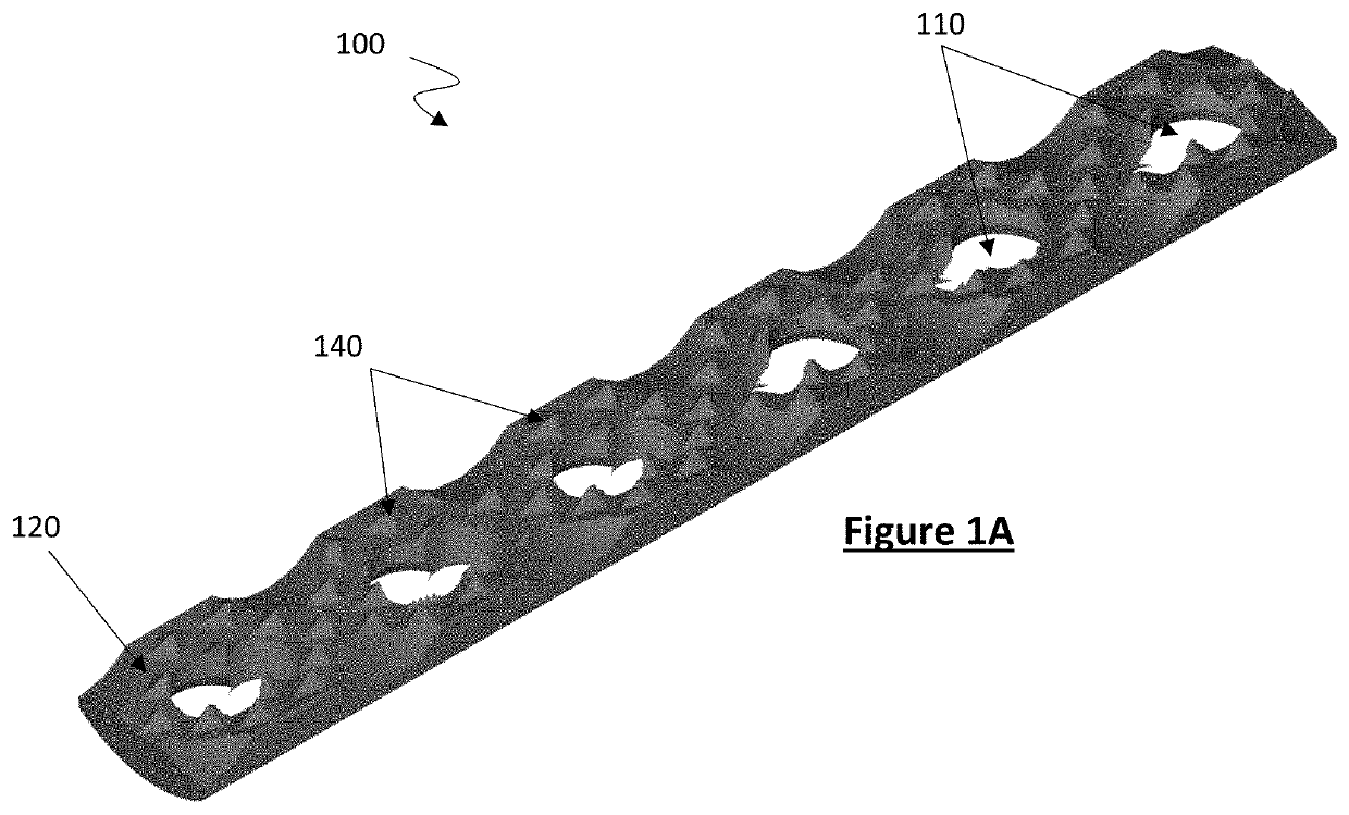
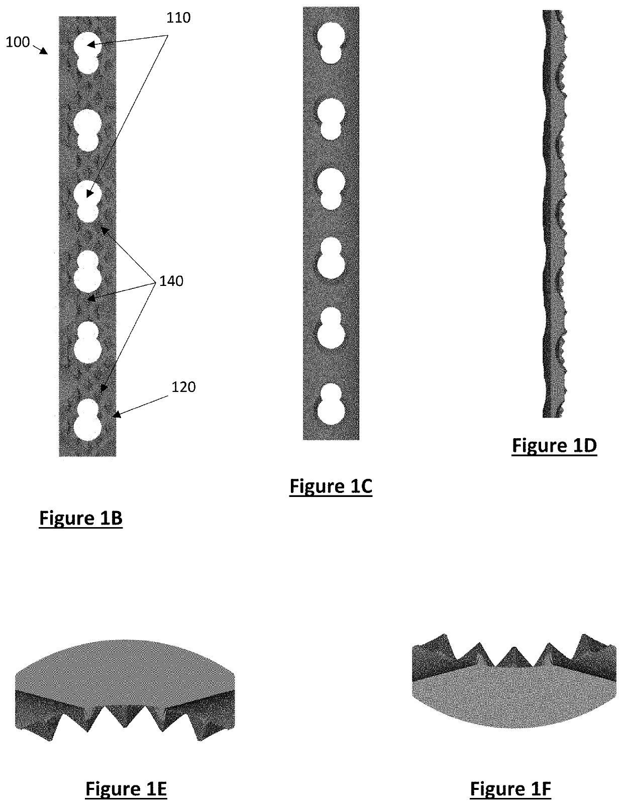
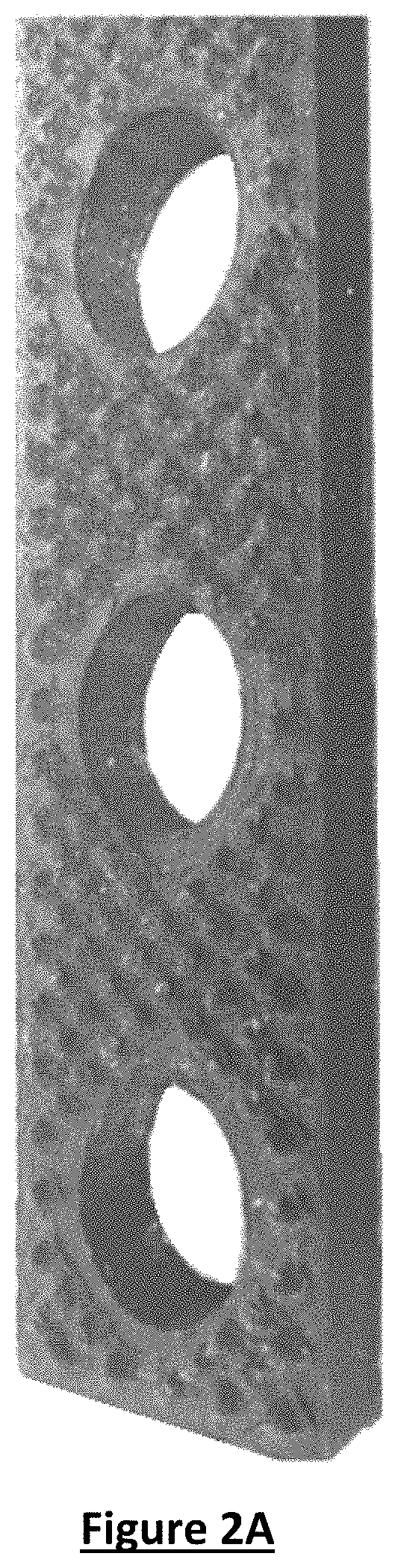
[0051]The disclosure and the various features and advantageous details thereof are explained more fully with reference to the non-limiting embodiments and examples that are described and / or illustrated in the accompanying drawings and detailed in the following description. It should be noted that the features illustrated in the drawings are not necessarily drawn to scale, and features of one embodiment may be employed with other embodiments as the skilled artisan would recognize, even if not explicitly stated herein. Descriptions of well-known components and processing techniques may be omitted so as to not unnecessarily obscure the embodiments of the disclosure. The examples used herein are intended merely to facilitate an understanding of ways in which the disclosure may be practiced and to further enable those of skill in the art to practice the embodiments of the disclosure. Accordingly, the examples and embodiments herein should not be construed as limiting the scope of the dis...


PUM


Abstract

Disclosed are devices, systems and related surgical methods for improving the fixation and / or durability of bone implants and / or components thereof for cervical fracture fixation and / or other orthopedic procedures.

Description

CROSS-REFERENCE TO RELATED APPLICATIONS[0001]This application is a continuation-in-part of U.S. Utility patent application Ser. No. 17 / 714,980 entitled “ORTHOPAEDIC FRICTION PLATE,” filed Apr. 6, 2022, which claims the benefit of U.S. Provisional Application No. 63 / 171,910 entitled “ORTHOPAEDIC FRICTION PLATE,” filed Apr. 7, 2021. This application further claims the benefit of U.S. Provisional Application No. 63 / 181,142 entitled “CERVICAL FRICTION PLATE,” filed Apr. 28, 2021. Each of these above-referenced disclosures are hereby incorporated by reference herein in their entireties.FIELD OF THE INVENTION[0002]The present subject matter relates generally to surgical devices and more specifically to devices, system and methods for spinal fusion, fracture fixation and / or other orthopedic procedures of the cervical spine.BACKGROUND OF THE INVENTION[0003]Many bony fractures require stabilization that cannot be provided by external splints or casts—internal fixation is therefore required. ...

Claims


Application Information

Patent Timeline
IPC IPC(8): A61B17/70A61B17/80
CPCA61B17/7059A61B17/809A61B17/8014B33Y80/00B22F5/006B22F2999/00B22F2005/005
Inventor GARDNER, VANCEALEXANDER, GERALDDUFFIN, MATTHEWGORAB, ROBERTHELBER, RYANOLUYEDE, OLUWADAMILOLAQUILLIGAN, EDWARDPRIETTO, CARLOSSMITH, JEREMYWHITE, JON
Owner ORTHOPAEDIC EDUCATION & RES INST D B A HOAG ORTHOPEDICS
Why Eureka
Try Eureka