
Aerodyne with antenna and associated arrangement method

a technology of aerodyne and antenna, applied in the field of aerodyne, can solve the problems of increasing the drag of the aerodyne, fuel consumption, and the need for substantial mechanical and aerodynamic tune-up, and achieve the effect of saving time and budg

Pending Publication Date: 2022-10-06
AIRBUS DEFENCE & SPACE +1
View PDF2 Cites 0 Cited by
  • Summary
  • Abstract
  • Description
  • Claims
  • Application Information

AI Technical Summary

Benefits of technology

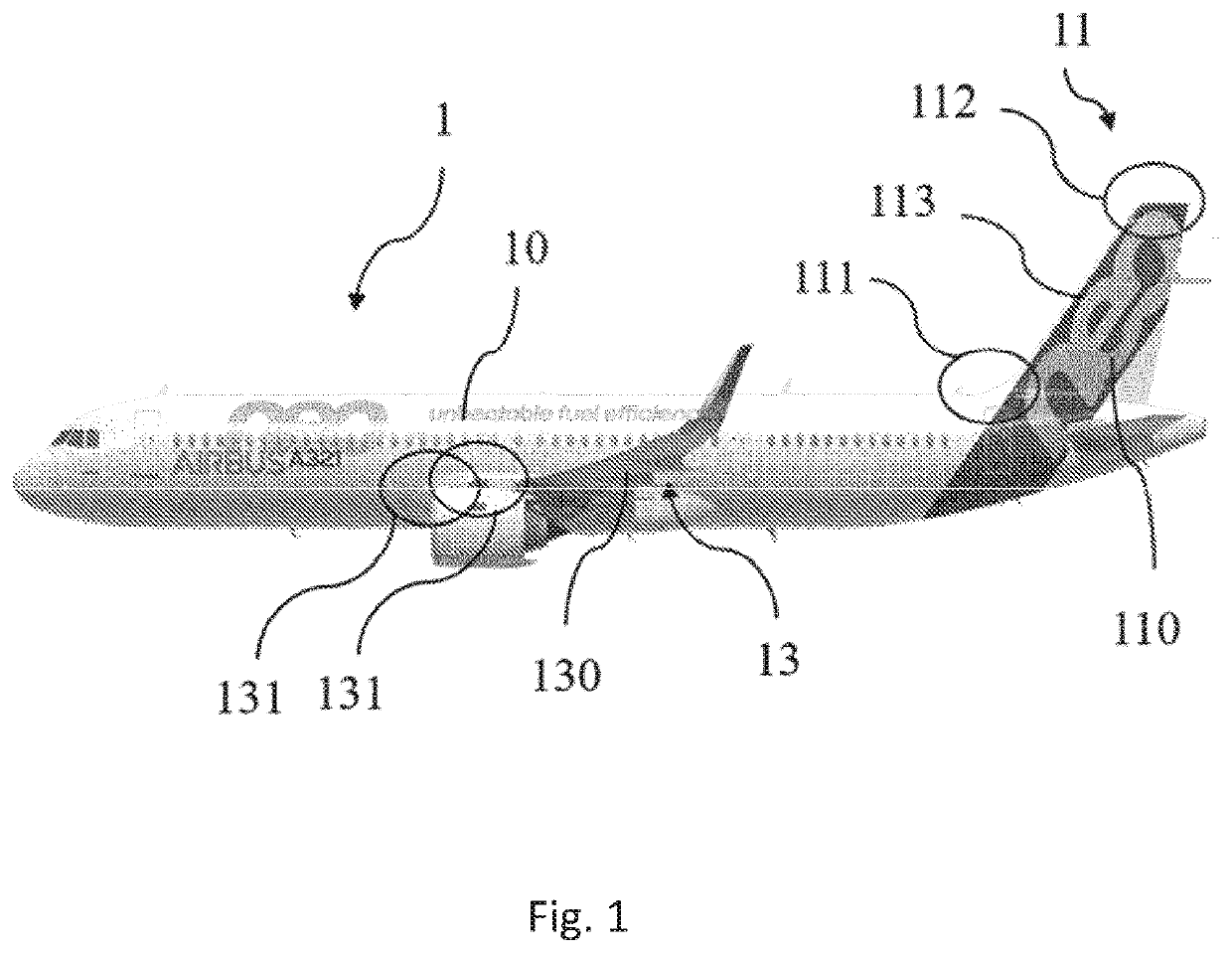
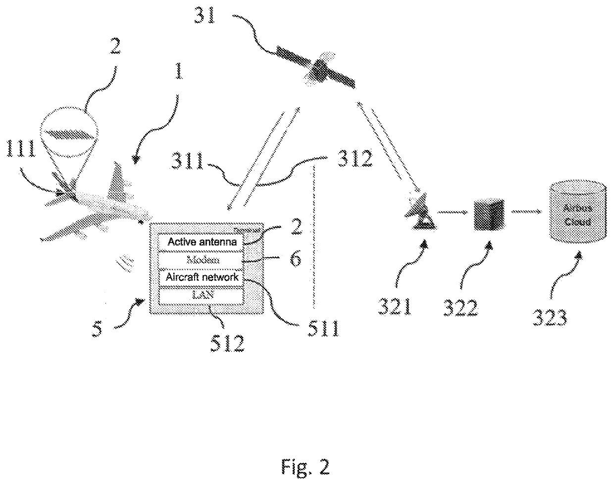
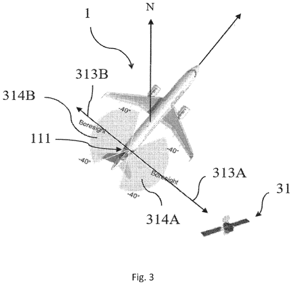
The invention allows for easy installation and low maintenance of the antennas on an aerodynie. It also ensures good reliability of communication by radio waves and preserves the aerodynamic properties of the aerod externe design. The positioning of the antennas can be flexible, with some placed on the dorsal fin, top and bottom portions, and other on one or two wings. Additionally, the multiple antennas distributed at different locations on the aerod+)

Problems solved by technology

However, such arrangements have the drawback of increasing the drag of the aerodyne, and therefore fuel consumption.
In addition, substantial mechanical and aerodynamic tune-ups are required, at the cost of investment in time and budget.
In addition, a flight authorisation is acquired only subject to satisfactory analyses and tests.
The maintenance of corresponding antennas, becoming frequently necessary by difficult navigation environments (vibrations, temperature, mechanical stresses, etc.), also requires a long downtime of the aerodynes, thus increasing the cost price over time.
However, such a system provides information limited to a front view, and is not suitable, for example, for communications with satellites or terrestrial relays.
However, such an embodiment implements mechanisms that require installations requiring time and accuracy, and relatively frequent maintenance.
In addition, in the deployed mode, it affects the aerodynamics of the aircraft.
What is more, its positioning makes it especially effective for communications with terrestrial antennas, but not very suitable for satellite communications.
However, it has the drawbacks of restrictive requirements on the antenna positioning, closely related to the configuration of the wing, and a high exposure to external stresses.
Indeed, it goes against the apparently antagonistic requirements of good aerodynamic behaviour of the airfoil and of efficient transmission of radio waves.

Method used


Image

  • Aerodyne with antenna and associated arrangement method
  • Aerodyne with antenna and associated arrangement method
  • Aerodyne with antenna and associated arrangement method

Examples


Embodiment Construction

[0088]The present description illustrates the principles disclosed such that a person skilled in the art is able to design various modalities which, although not explicitly described or shown, incorporate the principles of the description and fall within its spirit and its scope.

[0089]All of the examples and the conditional language disclosed herein are intended for explanatory purposes to help the reader understand the principles of the description and the concepts developed by the inventors to extend the state of the art, and should be interpreted as not being restricted to such specifically described examples and conditions.

[0090]In addition, all mentions of principles, aspects and embodiments of the description, as well as of corresponding specific examples, are intended to cover both structural and functional equivalents. Such equivalents are also intended to include both known equivalents and equivalents that will be developed in the future, namely all developed elements that ...


PUM


Abstract

A method for arranging a set of antennas capable of transmitting or receiving in a radio frequency range in an existing aerodyne implemented either during an initial installation operation, or in a subsequent maintenance or update operation is disclosed. The method includes removing at least one component of a structural element external to the bearing surface of the existing aerodyne, the component being substantially transparent to the radio frequency range; installing the set of antennas in a zone exposed by the removal in the step; fitting an electronic and electrical harness connecting the set of antennas to a radio communications system and to a power supply inside the fuselage; re-forming the external structural element in such a way as to cover the installed set of antennas.

Description

TECHNICAL FIELD[0001]The present invention relates to an aerodyne comprising one or more antenna(s), as well as an outer structural assembly and a corresponding arrangement method. In particular, it applies to fixed-wing aerodynes, such as aircrafts or gliders.PRIOR ART[0002]The presence of antennas in aerodynes appears to be necessary or useful for multiple communications functions, including the acquisition of information required for the proper progress of the flight and the transmission of data relating to the covered course. Among these functions, aircraft connectivity could also provide an Internet connection, in particular by WiFi (standing for “Wireless Fidelity”), to passengers and to the crew.[0003]An important aspect relating to antennas consists in their positioning. In particular, it is known to arrange radome systems in the upper part of the aerodyne, on the fuselage. However, such arrangements have the drawback of increasing the drag of the aerodyne, and therefore fue...

Claims


Application Information

Patent Timeline
IPC IPC(8): H01Q1/28H01Q21/06H01Q21/28
CPCH01Q1/287H01Q21/065H01Q21/28B64C1/36H01Q1/28
Inventor MAISONNAT, THIBAULTPEYRUCAIN, ERICLAGARRIGUE, ALAINGINEST, VALERY
Owner AIRBUS DEFENCE & SPACE
Learn More