Capacitive sensing device

a capacitive sensing and capacitive technology, applied in the field can solve problems such as sensing errors, and achieve the effect of improving the sensing quality of capacitive sensing devices

Pending Publication Date: 2022-09-29
EGIS TECH
View PDF0 Cites 2 Cited by
  • Summary
  • Abstract
  • Description
  • Claims
  • Application Information

AI Technical Summary

Benefits of technology

[0003]The disclosure provides a capacitive sensing device, which can improve the sensing quality of the capacitive sensing device, and avoid the situation

Problems solved by technology

However, the electrodes have the characteristics of an antenna, which will reflect changes in the electric field in the environment (such as changes in am

Method used


Image

  • Capacitive sensing device
  • Capacitive sensing device
  • Capacitive sensing device

Examples


Embodiment Construction

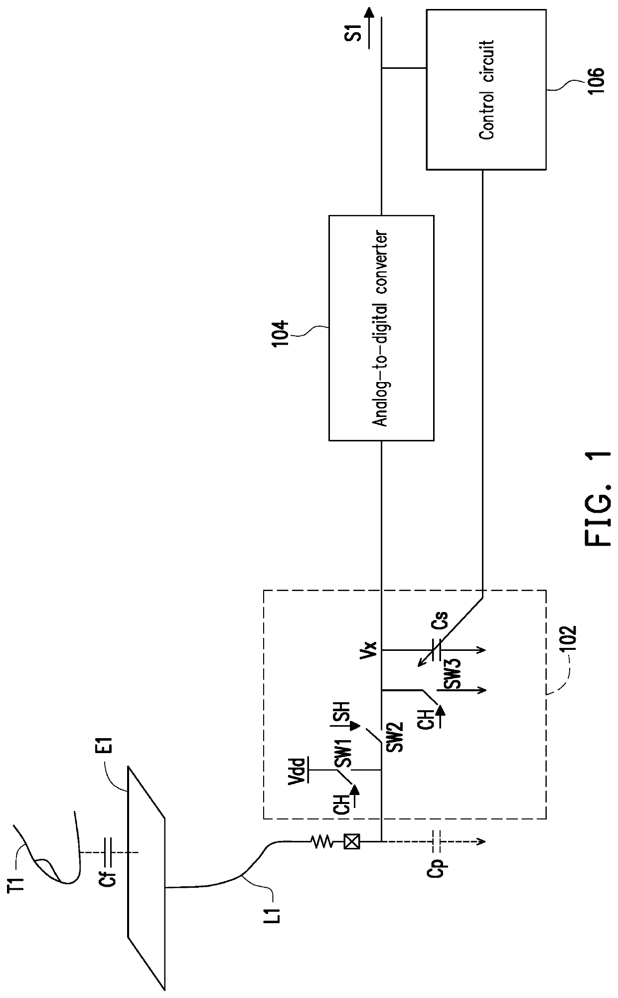
[0014]FIG. 1 is a schematic diagram of a capacitive sensing device according to an embodiment of the disclosure. Please refer to FIG. 1. The capacitive sensing device includes a sensing electrode E1, a sensing circuit 102, an analog-to-digital converter 104 and a control circuit 106. The sensing electrode E1 may be coupled to the input terminal of the sensing circuit 102 through a sensing signal line L1, and the analog-to-digital converter 104 is coupled to the output terminal of the sensing circuit 102 and the control circuit 106.

[0015]The sensing electrode E1 may be used to receive the touch operation of a touch tool T1, and for example, in this embodiment, it may receive the touch operation of a finger, but it is not limited thereto. The sensing circuit 102 may sense the capacitance change of a sensing capacitor Cf between the touch tool T1 and the sensing electrode E1 to generate a sensing signal to the analog-to-digital converter 104. The analog-to-digital converter 104 may con...


PUM


Abstract

A capacitive sensing device is provided. A control circuit adjusts a capacitance value of an adjustable capacitor unit according to a digital sensing signal converted from a sensing signal by an analog-to-digital converter, such that the capacitance value of the adjustable capacitor unit approaches a background parasitic capacitor.

Description

TECHNICAL FIELD[0001]The disclosure relates to a sensing device, and more particularly to a capacitive sensing device.DESCRIPTION OF RELATED ART[0002]With the development of optoelectronic technology, proximity switching devices have been widely used in different machines, such as smart phones, ticketing systems for transportation vehicles, digital cameras, remote controls and liquid crystal displays. Common sensing devices capable of proximity switching include proximity sensors and capacitive touch switches. The capacitive touch switches determine the state of the switch by sensing the parasitic capacitor of its electrodes. However, the electrodes have the characteristics of an antenna, which will reflect changes in the electric field in the environment (such as changes in ambient humidity or the influence of radio frequency signals) and affect the sensing results of the capacitive touch switch, thereby causing sensing errors.SUMMARY[0003]The disclosure provides a capacitive sensi...

Claims


Application Information

Patent Timeline
IPC IPC(8): H03K17/96
CPCH03K17/962H03K2217/96074H03K2217/96071H03K2217/960705G01R27/2605
Inventor LIU, SHIUE-SHIN
Owner EGIS TECH
Why Eureka
Try Eureka