Optical structure for producing decorative lighting effects

a technology of optical structure and decorative lighting, applied in the direction of instruments, lighting and heating apparatus, semiconductor devices of light sources, etc., can solve the problems of increasing the material cost, affecting the appearance of users, and affecting the effect of light bulb performan

Pending Publication Date: 2022-09-22
SIGNIFY HLDG BV
View PDF1 Cites 0 Cited by
  • Summary
  • Abstract
  • Description
  • Claims
  • Application Information

AI Technical Summary

Benefits of technology

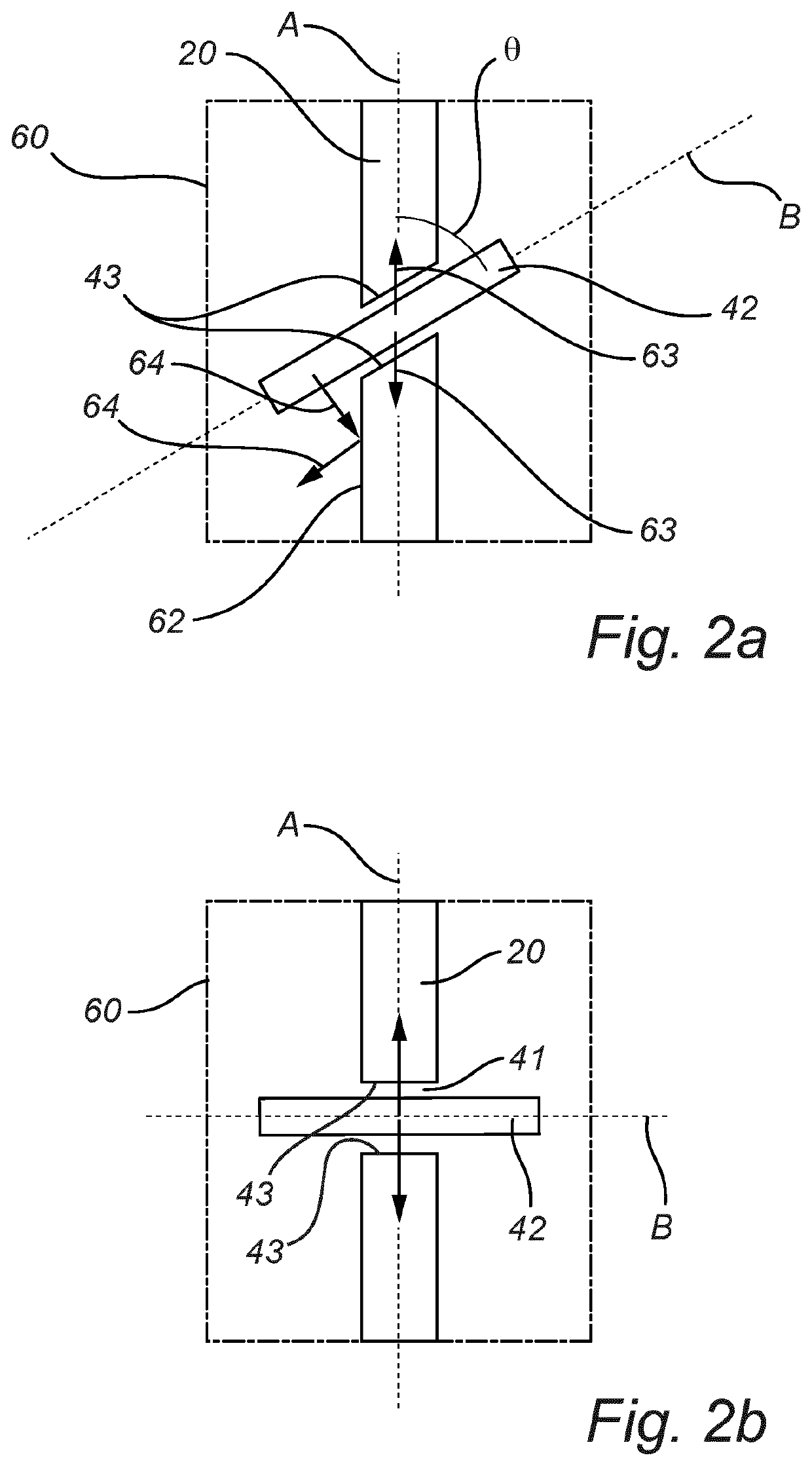
This patent aims to improve the decorative lighting effects of LED-filaments in lighting devices. It suggests using an optical structure that directly mounts the LED-filament on an elongated optical element, which guides and holds the LED-filament in place. This structure provides the required mechanical support and stability, and allows for the optical properties of the optical element to produce desired effects. The optical element can also have a reflecting surface that at least partially reflects the light emitted from the LED-filament, allowing for more complex decorative lighting effects. The optical element can have curved features that redirect the light emitted from the LED-filament and allow for customizable spatial light distributions. Overall, this invention offers an improved and customizable optical structure for producing decorative lighting.

Problems solved by technology

Even though this light bulb disclosed in the prior art aims at providing a more uniform and decorative lighting, there are substantial drawbacks associated with the disclosed light bulb.
This in turn increases the material cost and nevertheless has an unpleasant appearance to the users as the wire supports and the central structure alter the aesthetic appearance of the LED-filament and may even distort the intended lighting effects.

Method used


Image

  • Optical structure for producing decorative lighting effects
  • Optical structure for producing decorative lighting effects
  • Optical structure for producing decorative lighting effects

Examples


Embodiment Construction

[0051]The present invention will now be described more fully hereinafter with reference to the accompanying drawings, in which currently preferred embodiments of the invention are shown. This invention may, however, be embodied in many different forms and should not be construed as limited to the embodiments set forth herein; rather, these embodiments are provided for thoroughness and completeness, and fully convey the scope of the invention to the skilled person.

[0052]FIG. 1a shows a lighting device such as a light bulb / lamp 61 comprising an optical structure 10, including one or several, in the illustrated case two, LED filaments 30 supported by an elongated optical element 20 according to an embodiment of the invention.

[0053]The LED-filament 30 is preferably made of a flexible substrate. For example, a plurality of solid state light sources such as light emitting diodes (LEDs) are placed on a flexible PCB (printed circuit board) to produce the flexible LED-filament 30. An encapsu...


PUM


Abstract

The present invention relates to an optical structure for producing a decorative lighting effect in a lighting device, and a lighting device comprising at least one of the optical structure, wherein the optical structure comprises an optical element formed in one piece and comprising at least one opening; and an LED-filament comprising a substrate and a plurality of light sources arranged on the substrate, the substrate being at least partly made of a flexible material; wherein the at least one opening is adapted to receive the LED-filament such that a portion of the LED-filament extends through and is at least partly enclosed by a surrounding wall of the at least one opening such that the LED-filament is guided by and held in place by means of the at least one opening of the optical element and wherein light emitted from the LED-filament interacts with the optical element.

Description

FIELD OF THE INVENTION[0001]The present invention relates to an optical structure having a flexible filament for producing decorative lighting effects in a lighting device. The present invention also relates to a lighting device comprising such an optical structure, and to a method of manufacturing of such an optical structure.BACKGROUND OF THE INVENTION[0002]Incandescent lamps are rapidly being replaced by light emitting diode (LED)-based lighting solutions such as LED-filament lamps. It is nevertheless appreciated and desired by the users for these lamps to have the look of an incandescent light bulb. For this purpose, one can simply make use of the infrastructure for producing incandescent lamps based on glass and replace the conventional filament with LED filaments. One of the concepts is based on LED filaments made of flexible material and placed in such a light bulb. The appearances of these lamps are highly appreciated as they achieve omnidirectional lighting, look highly dec...

Claims


Application Information

Patent Timeline
IPC IPC(8): F21K9/232F21V8/00
CPCF21K9/232G02B6/0068F21K9/235F21K9/61F21K9/68F21V19/002F21Y2115/10G02B6/0021G02B6/006
Inventor VAN BOMMEL, TIESHIKMET, RIFAT ATA MUSTAFA
Owner SIGNIFY HLDG BV
Why Eureka
Try Eureka