Modular rain garden system

Pending Publication Date: 2022-08-25
ILLMAN SUSAN
View PDF0 Cites 0 Cited by
  • Summary
  • Abstract
  • Description
  • Claims
  • Application Information

AI Technical Summary

Benefits of technology

The patent describes a rain garden planter that has corrugated side walls and end sections for increased strength. The planter also has an overflow means to prevent soil media from becoming water logged for too long. These features make the planter more durable and better able to handle the volume of rainwater that is directed to it.

Problems solved by technology

Storm water drainage in cities is a current challenge for urban planners and engineers.
The need for car parking for example, results in many suburban front gardens being paved over, adding to water runoff in storm events to an already overburdened drainage system.
Scientists also predict an increase in heavy rain fall events in the coming decades, raising the likelihood of severe and damaging flooding in cities.
Current initiatives to reduce run off tend to be bespoke, are limited in impact, and expensive to install, requiring considerable engineering input.
Replacing underground drainage pipes for larger higher capacity pipes can be highly disruptive to communities, and prohibitively expensive.
Excavating small rain gardens in paved surfaces, to intercept, attenuate and store rain water in engineered surrounds is problematic due to the load bearing and structural requirements of such surfaces.
Rain gardens in soft landscape areas can also cause problems with soil erosion and ground stability.
At the same time, there is great resistance from the highways engineering profession for water to be collected within the soil adjacent to highways, due to the potential for destabilisation of the road kerbs and edgings.

Method used


Image

  • Modular rain garden system
  • Modular rain garden system
  • Modular rain garden system

Examples


Embodiment Construction

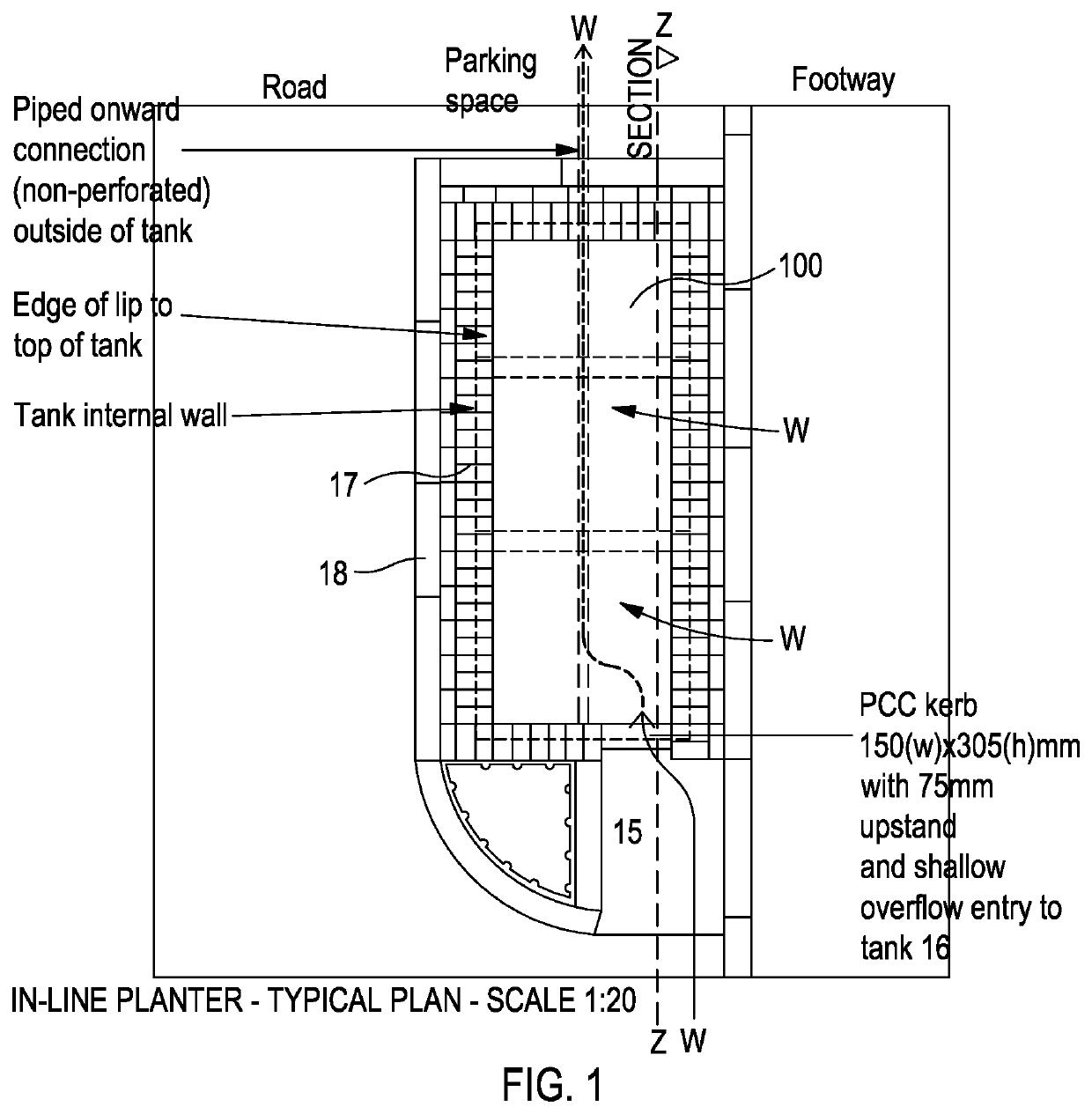
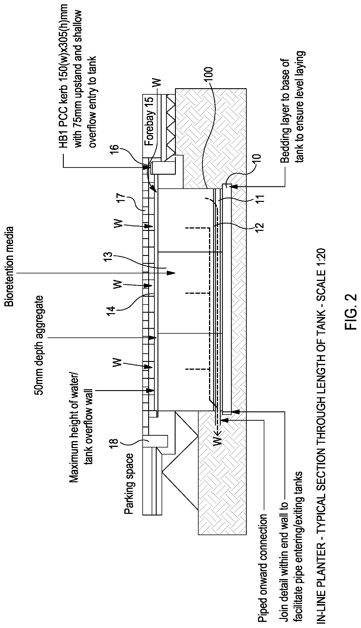
[0058]With reference to FIGS. 1 and 2, a typical urban installation for a modular rain garden system in accordance with the invention is shown. The location is a planted bed adjacent a line of parking spaces on a road. The tank or trough formed by the modular rain garden system is shown generally as 100 and will be described in more detail with reference to the other figures below. In terms of this example installation, the tank or trough 100 is sunk into a hole which is lined at the bottom with a bedding layer 10. The trough 100 has an internal perforated pipe 11 and a grid layer 12, above which the trough is filled with bioretention media 13, such as soil media. A 50 mm layer of aggregate 14 forms the top layer.

[0059]A forebay 15 is provided to control the flow of water into the trough 100 and act as a silt and debris filter. A pre-cast concrete kerb 16 provides an overflow lip (75 mm in this example), over which the water W passes when there is a high enough flow of water into th...


PUM


Abstract

The invention provides a modular rain garden system comprising a plurality of preformed channel sections 310 and two end panels 320. The channel section 310 and end panels 320 are configured to form a trough 300 when assembled to receive rainwater runoff. At least one end of the channel section has an engaging profile configured to engage with another channel section or one of the end panels. Divider panels 330 are provided to separate the trough into compartments, to provide additional strength or rigidity to the trough or to control or limit the flow of water between compartments. The side walls 312 of the channel sections, the end panel 320 and the divider panels 330 are corrugated by means of projections or grooves 313, 321 and 331 respectively to increase the strength and load-bearing capability of the components.

Description

TECHNICAL FIELD[0001]The present invention relates to rain gardens, which are used to intercept, attenuate and temporarily store rain water runoff, usually in urban areas having impervious surfaces such as roads, driveways, pavements, roofs and the like.BACKGROUND[0002]Storm water drainage in cities is a current challenge for urban planners and engineers. In many urban areas, the existing drainage infrastructure was built for a different era and population. The need for car parking for example, results in many suburban front gardens being paved over, adding to water runoff in storm events to an already overburdened drainage system.[0003]Scientists also predict an increase in heavy rain fall events in the coming decades, raising the likelihood of severe and damaging flooding in cities.[0004]Current initiatives to reduce run off tend to be bespoke, are limited in impact, and expensive to install, requiring considerable engineering input. Replacing underground drainage pipes for larger...

Claims


Application Information

Patent Timeline
IPC IPC(8): E03F1/00E03F5/10
CPCE03F1/005E03F5/101E03F5/106E03F1/002A01G24/10A01G24/20A01G24/30E03F1/00E03F5/10
Inventor ILLMAN, SUSAN
Owner ILLMAN SUSAN
Why Eureka
Try Eureka