
Electrical connector with electromagnetic shielding function

a technology of electromagnetic shielding and electrical connectors, applied in the direction of electrical apparatus, connection, coupling device connections, etc., can solve the problems of crosstalk between high-frequency differential cables, incomplete signals affecting transmission quality, and affecting signal transmission characteristics of connectors

Pending Publication Date: 2022-07-28
JESS-LINK PRODUCTS
View PDF2 Cites 0 Cited by
  • Summary
  • Abstract
  • Description
  • Claims
  • Application Information

AI Technical Summary

Benefits of technology

The present invention is an electrical connector with electromagnetic shielding function. It can cover the wire core of the cable and contact the shielding layer of the cable at the same time, providing efficient electromagnetic shielding. The connector can separate adjacent cables and generate electromagnetic shielding through protruding structures, preventing crosstalk between cables. The shielding component can adapt to cables with different wire diameters and cover the wire core and shielding layer to prevent interference from external electronic components, improving transmission quality and efficiency.

Problems solved by technology

The connector will suffer from electromagnetic interference or radio frequency interference, resulting in incomplete signals to affect the transmission quality.
Since the reduced distance between the cables is not conducive to the transmission of high-frequency signals, it is easy to cause crosstalk between the high-frequency differential cables.
Therefore, the signal transmission characteristics of the connector are affected due to the above-mentioned interference reasons.
At this time, there is no shielding layer protection between the cores of each cable, which may still cause crosstalk between the cables.
In addition, the stripped shielding layer may be exposed outside the cable, so that the shielding layer has a great influence on the resistance connection and insertion loss of the cable, thereby reducing the transmission quality of the cable.

Method used


Image

  • Electrical connector with electromagnetic shielding function
  • Electrical connector with electromagnetic shielding function
  • Electrical connector with electromagnetic shielding function

Examples


Embodiment Construction

[0029]For the sake of the advantages, spirits and features of the present invention can be understood more easily and clearly, the detailed descriptions and discussions will be made later by way of the embodiments and with reference of the diagrams. It is worth noting that these embodiments are merely representative embodiments of the present invention, wherein the specific methods, devices, conditions, materials and the like are not limited to the embodiments of the present invention or corresponding embodiments. Moreover, the devices in the figures are only used to express their corresponding positions and are not drawing according to their actual proportion.

[0030]In the description of this specification, the description with reference to the terms “a specific embodiment”, “another specific embodiment” or “parts of specific embodiments” etc. means that the specific feature, structure, material or feature described in conjunction with the embodiment include in at least one embodime...


PUM


Abstract

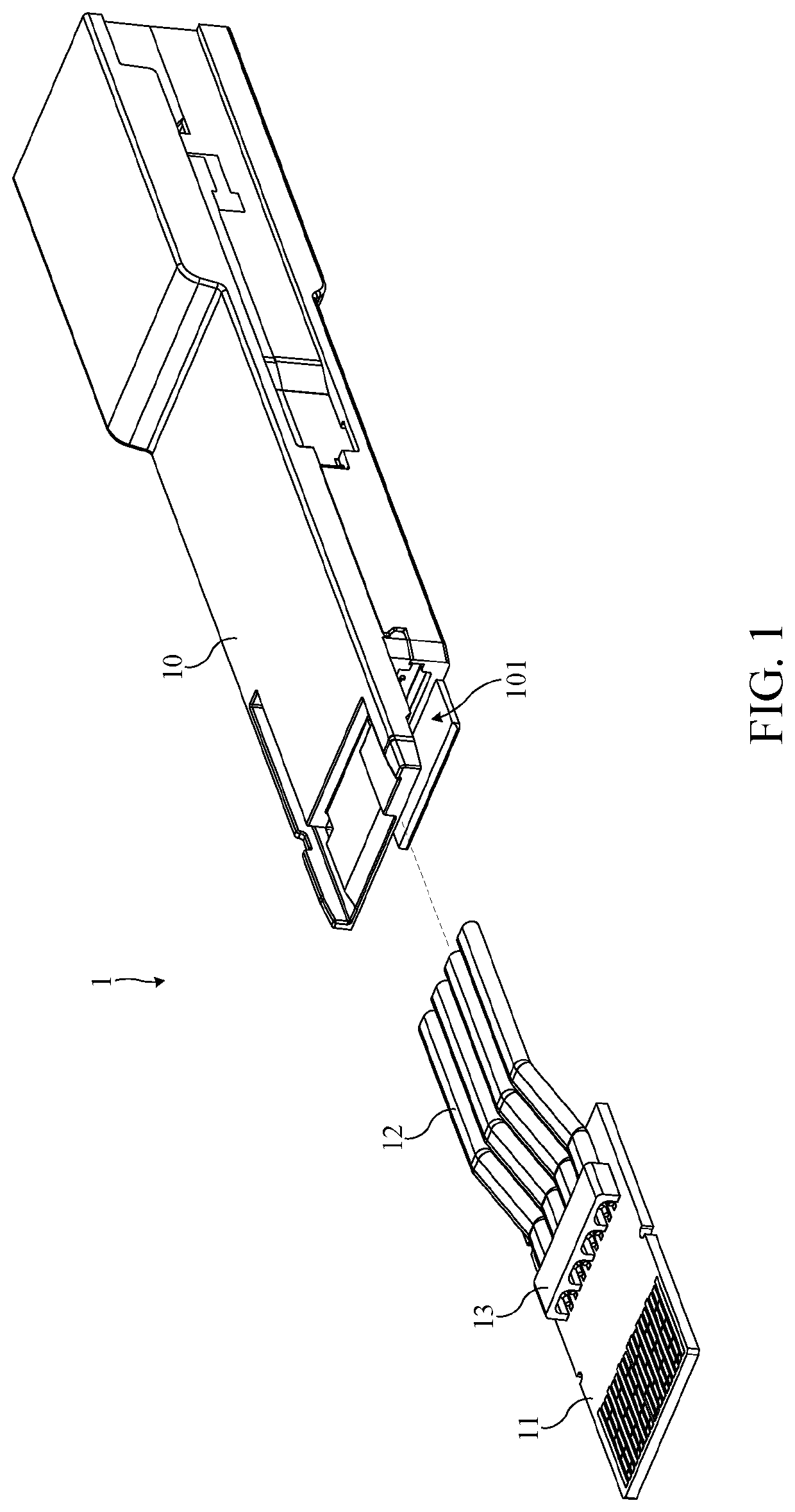
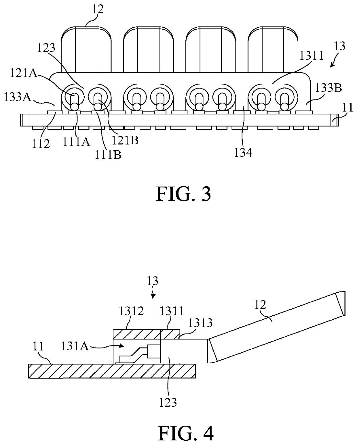
An electrical connector with electromagnetic shielding function includes a circuit board, a plurality of cables and a shielding component. The circuit board includes a plurality of conductive pads and a ground component. Each of cables includes a wire core and a shielding layer for covering the wire core. One end of the wire core is exposed from the shielding layer, and the wire cores of the cables are electrically connected to the conductive pads respectively. The shielding component is configured on the circuit board and electrically connected to the ground component. The shielding component forms a plurality of shielding grooves for covering the conductive pads and the cables. Each of the shielding grooves includes a contact portion configured to contact the shielding layer and a shielding portion configured to cover the exposed wire core of the cables to provide electromagnetic shielding to the cables.

Description

BACKGROUND OF THE INVENTION1. Field of the Invention[0001]The present invention relates to an electrical connector, and more particularly, to an electrical connector that can prevent inside and outside electromagnetic interference of the electrical connector and has an electromagnetic shielding function.2. Description of the Prior Art[0002]Connectors are connecting components and accessories for electrical signals, and the electronic devices translate and transmit the signal to each other through cables and connectors. That is to say, the connectors are the communicating bridges for the signals. The connectors are widely applied to cars and computer peripheral and communicating data applications, industries, military and aerospace industry, transportation, consumer electronics, medical treatments, instruments, commercial equipment and so on. Therefore, the connectors play an important role in many fields.[0003]In general, when the frequency of the signal transmitted by the connector...

Claims


Application Information

Patent Timeline
Patent Type & Authority Applications(United States)
IPC IPC(8): H01R13/6591H01R13/6594
CPCH01R13/65912H01R13/6594H01R12/62H01R13/65914H01R13/6593H01R13/6599H01R13/65915H01R13/65917H01R13/6595H01R13/6592
Inventor CHENG, CHIEH-MING
Owner JESS-LINK PRODUCTS
Learn More