


Quick Research
Generate reliable direction feasibility study reports for your R&D in just a few steps.

Technical Q&A
Discover and master advanced knowledge NOW. Basics, ideas, possibilities, all at once.

Find Solutions
As an expert in R&D theories, this can generate solutions to your technical problems instantly.

Evaluate Feasibility
Analyze your overall solution with one click, know your potential R&D risks in advance.

Monitor Landscape
Get weekly tech updates, stay abreast of the latest tech innovations and key insights.
Powered device and power over fiber system
a technology of fiber power supply and power supply, which is applied in the direction of fibre light guides, thermal-pv hybrid energy generation, instruments, etc., can solve the problems of energy loss, difficulty in etc., and achieve the effect of increasing or decreasing the intensity of feed ligh
- Summary
- Abstract
- Description
- Claims
- Application Information
AI Technical Summary
Benefits of technology
Problems solved by technology
Method used
Image

Examples
first embodiment
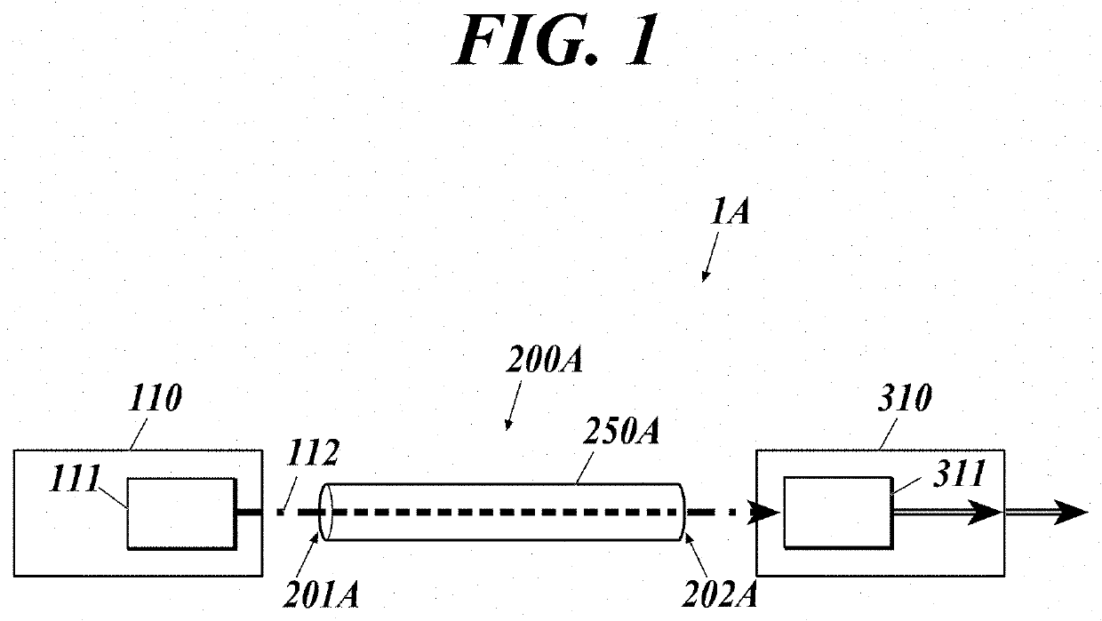
[0020]As shown in FIG. 1, a power over fiber (PoF) system 1A of this embodiment includes a power sourcing equipment (PSE) 110, an optical fiber cable 200A and a powered device (PD) 310.
[0021]In the present disclosure, a power sourcing equipment converts electric power into optical energy and supplies (sources) the optical energy, and a powered device receives (draws) the supplied optical energy and converts the optical energy into electric power.
[0022]The power sourcing equipment 110 includes a semiconductor laser 111 for power supply.
[0023]The optical fiber cable 200A includes an optical fiber 250A that forms a transmission path of feed light.
[0024]The powered device 310 includes a photoelectric conversion element 311.
[0025]The power sourcing equipment 110 is connected to a power source, and electrically drives the semiconductor laser 111 and so forth.
[0026]The semiconductor laser 111 oscillates with the electric power from the power source, thereby outputting feed light 112.
[0027]...
second embodiment
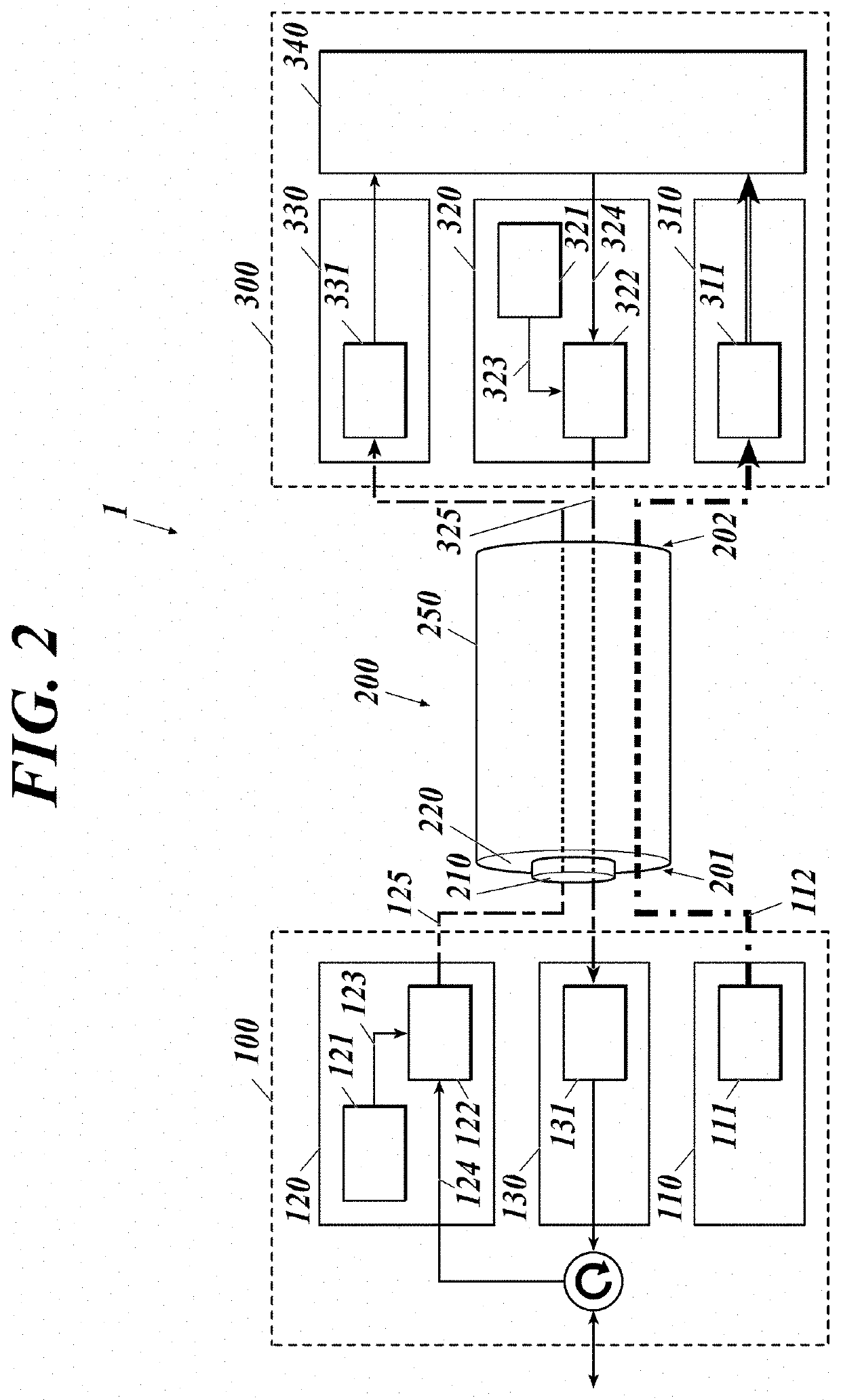
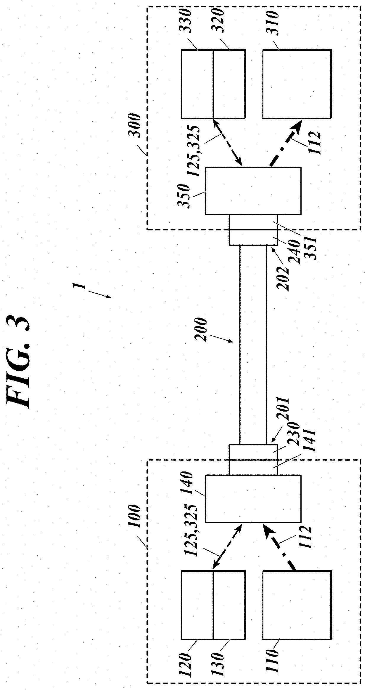
[0037]As shown in FIG. 2, a power over fiber (PoF) system 1 of this embodiment includes a power supply system through an optical fiber and an optical communication system therethrough, and includes: a first data communication device 100 including a power sourcing equipment (PSE) 110; an optical fiber cable 200; and a second data communication device 300 including a powered device (PD) 310.
[0038]The power sourcing equipment 110 includes a semiconductor laser 111 for power supply. The first data communication device 100 includes, in addition to the power sourcing equipment 110, a transmitter 120 and a receiver 130 for data communication. The first data communication device 100 corresponds to a data terminal equipment (DTE), a repeater or the like. The transmitter 120 includes a semiconductor laser 121 for signals and a modulator 122. The receiver 130 includes a photodiode 131 for signals.
[0039]The optical fiber cable 200 includes an optical fiber 250 including: a core 210 that forms a...
third embodiment
[0056]FIG. 5 is a block diagram of a powered device of a third embodiment to which a loss reducing means is applied. In FIG. 5, the components same as those described above are denoted by the same reference signs, and detailed descriptions thereof are omitted.
[0057]A powered device 310C of the third embodiment includes a photoelectric conversion element 311 that receives and converts the feed light 112 into electric power, a thermoelectric conversion element 314 disposed such that heat can be conducted thereto from the photoelectric conversion element 311, a second power line 312 that transmits electric power from the photoelectric conversion element 311 to a load 390, a first power line 315 that transmits electric power from the thermoelectric conversion element 314 to the load 390, and a current backflow prevention circuit 319 disposed on the power lines 312, 315. At the light receiving side of the photoelectric conversion element 311, a lens 313 may be disposed.
[0058]The load 390...
PUM
 Abstract
Description
Claims
Application Information
 - R&D Engineer
- R&D Manager
- IP Professional
- Industry Leading Data Capabilities
- Powerful AI technology
- Patent DNA Extraction
Browse by: Latest US Patents, China's latest patents, Technical Efficacy Thesaurus, Application Domain, Technology Topic, Popular Technical Reports.
© 2024 PatSnap. All rights reserved.Legal|Privacy policy|Modern Slavery Act Transparency Statement|Sitemap|About US| Contact US: help@patsnap.com