
Methods, systems, and apparatuses to facilitate providing and sustaining a laminar flow of a fluid across a vessel

a technology of providing and sustaining a laminar flow and fluid, which is applied in the direction of waterborne vessels, hulls, vessel construction, etc., can solve the problems of inability to reduce viscosity, current technologies do not facilitate the installation of a system in a displacement vessel during construction, and deficient techniques for facilitating laminar flow

Pending Publication Date: 2022-07-14
PARKER MARITIME TECH LLC
View PDF0 Cites 2 Cited by
  • Summary
  • Abstract
  • Description
  • Claims
  • Application Information

AI Technical Summary

Benefits of technology

The patent describes a system that helps create a smooth flow of fluid across a vessel, which can reduce resistance, reduce noise, and prevent the growth of marine organisms on the vessel's surface. This system also improves fuel efficiency and utilizes the benefits of a smooth flow. It includes air compressor units that can eliminate air supply. Overall, the system helps to create a more effective and efficient vessel design.

Problems solved by technology

Existing techniques for facilitating providing and sustaining a laminar flow of a fluid across a vessel are deficient with regard to several aspects.
For instance, current technologies do not reduce viscous resistance (RV) across a greater surface area but focus solely upon the flat-bottom portion of the wetted hull.
Furthermore, current technologies do not facilitate installation of a system in a displacement vessel during construction, retrofitting, while underway and / or in-port but employ multiple hull access cuts to create air distribution cavities, and require dry-docking to support the installation.
Moreover, current technologies do not facilitate operational and environmental enhancements resultant from employing the system on the displacement vessel.

Method used


Image

  • Methods, systems, and apparatuses to facilitate providing and sustaining a laminar flow of a fluid across a vessel
  • Methods, systems, and apparatuses to facilitate providing and sustaining a laminar flow of a fluid across a vessel
  • Methods, systems, and apparatuses to facilitate providing and sustaining a laminar flow of a fluid across a vessel

Examples


Embodiment Construction

[0051]The following description is presented to enable a person of ordinary skill in the art to make and use the various embodiments. Descriptions of specific devices, techniques, and applications are provided only as examples. Various modifications to the examples described herein will be readily apparent to those of ordinary skill in the art, and the general principles defined herein may be applied to other examples and applications without departing from the spirit and scope of the various embodiments. Thus, the various embodiments are not intended to be limited to the examples described herein and shown, but are to be accorded the scope consistent with the claims.

[0052]As a preliminary matter, it will readily be understood by one having ordinary skill in the relevant art that the present disclosure has broad utility and application. As should be understood, any embodiment may incorporate only one or a plurality of the above-disclosed aspects of the disclosure and may further inc...


PUM


Abstract

The present disclosure relates generally to the field of facilitating a laminar flow and sound mitigation between a wetted hull of a vessel and surrounding fluid. More specifically, the present disclosure includes methods, systems, and apparatuses to facilitate providing and sustaining a laminar flow of a fluid across a vessel. A system for sustaining laminar flow of a fluid across a vessel comprising a main control unit. The main control unit comprises one or more air compressor units configured to generate air. An integrated longitudinal air distribution assembly is secured to a wetted hull of the vessel. The distribution assembly comprises a series of air dispersal modules configured to distribute the generated air across the wetted hull of the vessel to create at least one air layer between the wetted hull of the vessel and the fluid to sustain the laminar flow of the fluid across the vessel.

Description

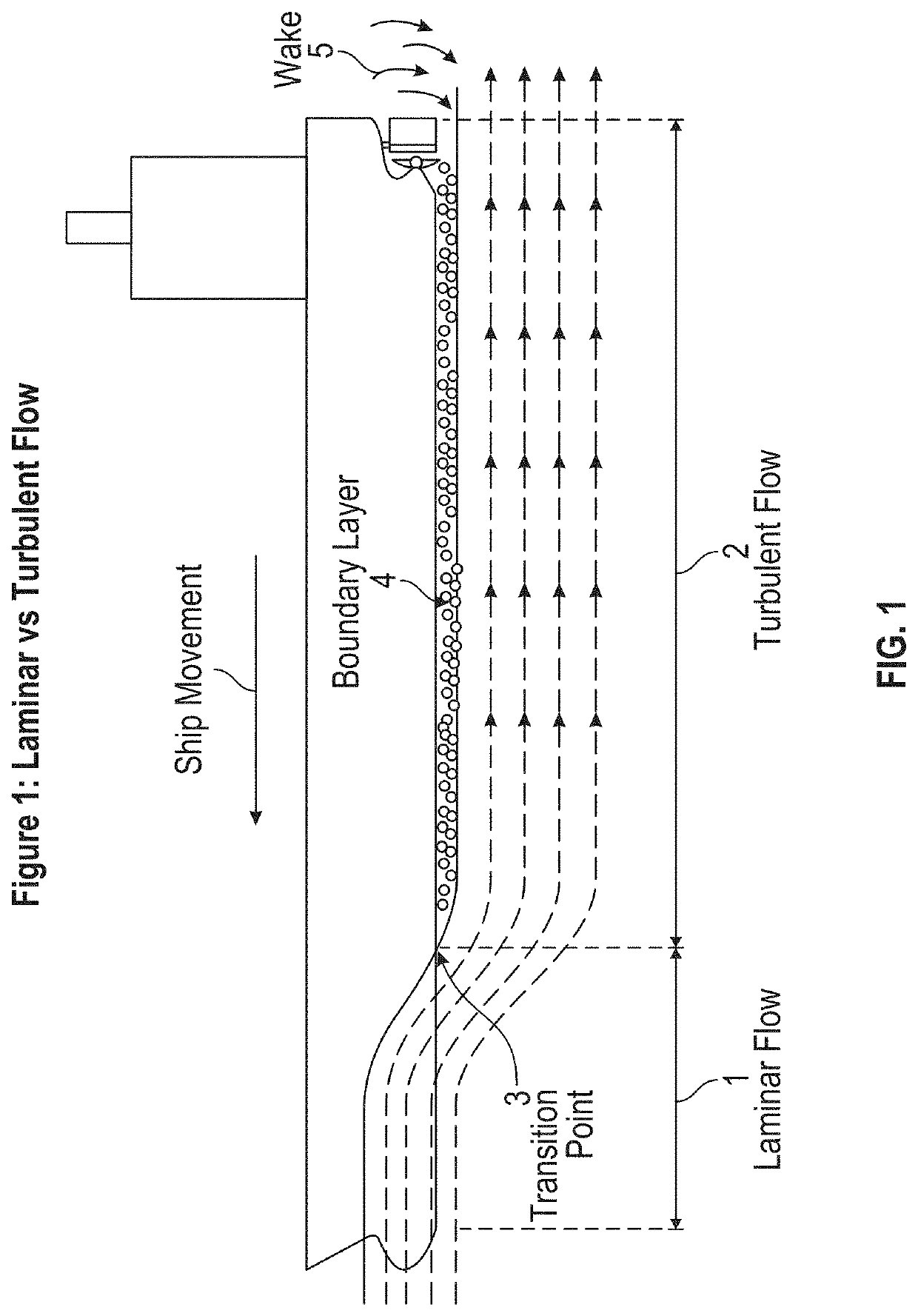
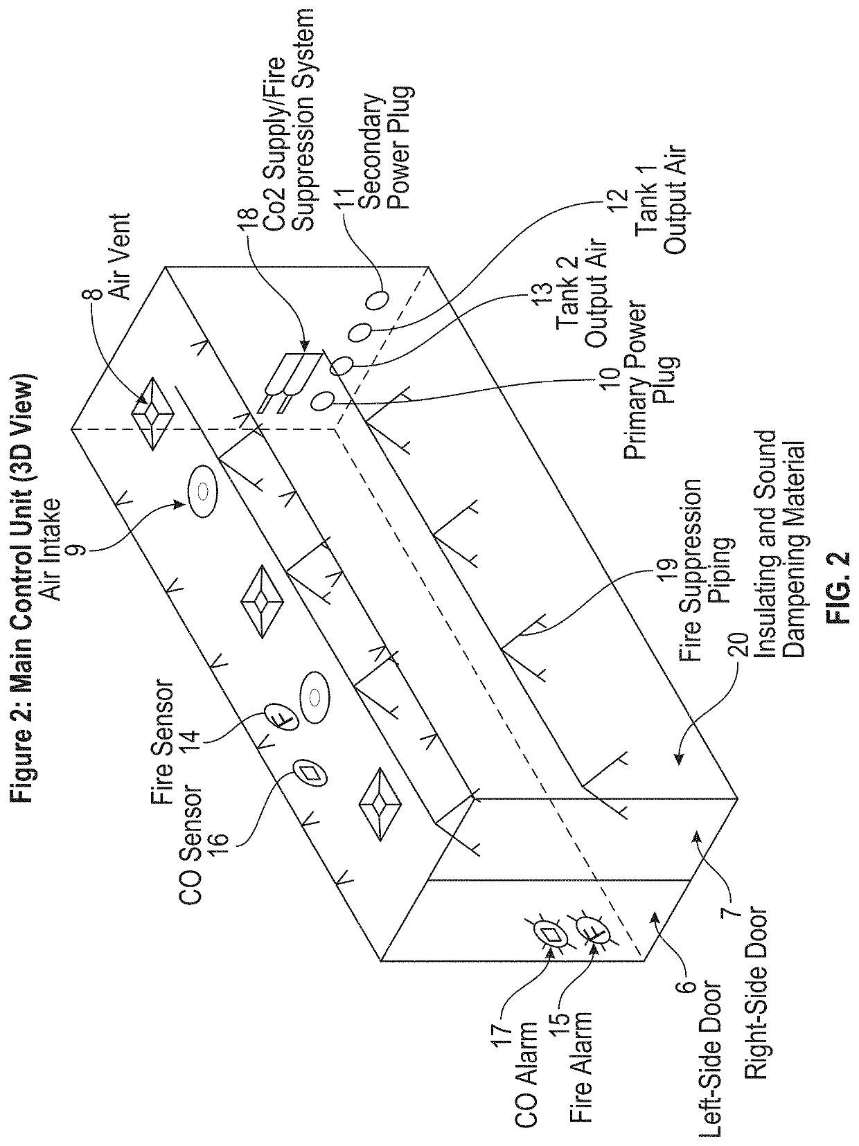
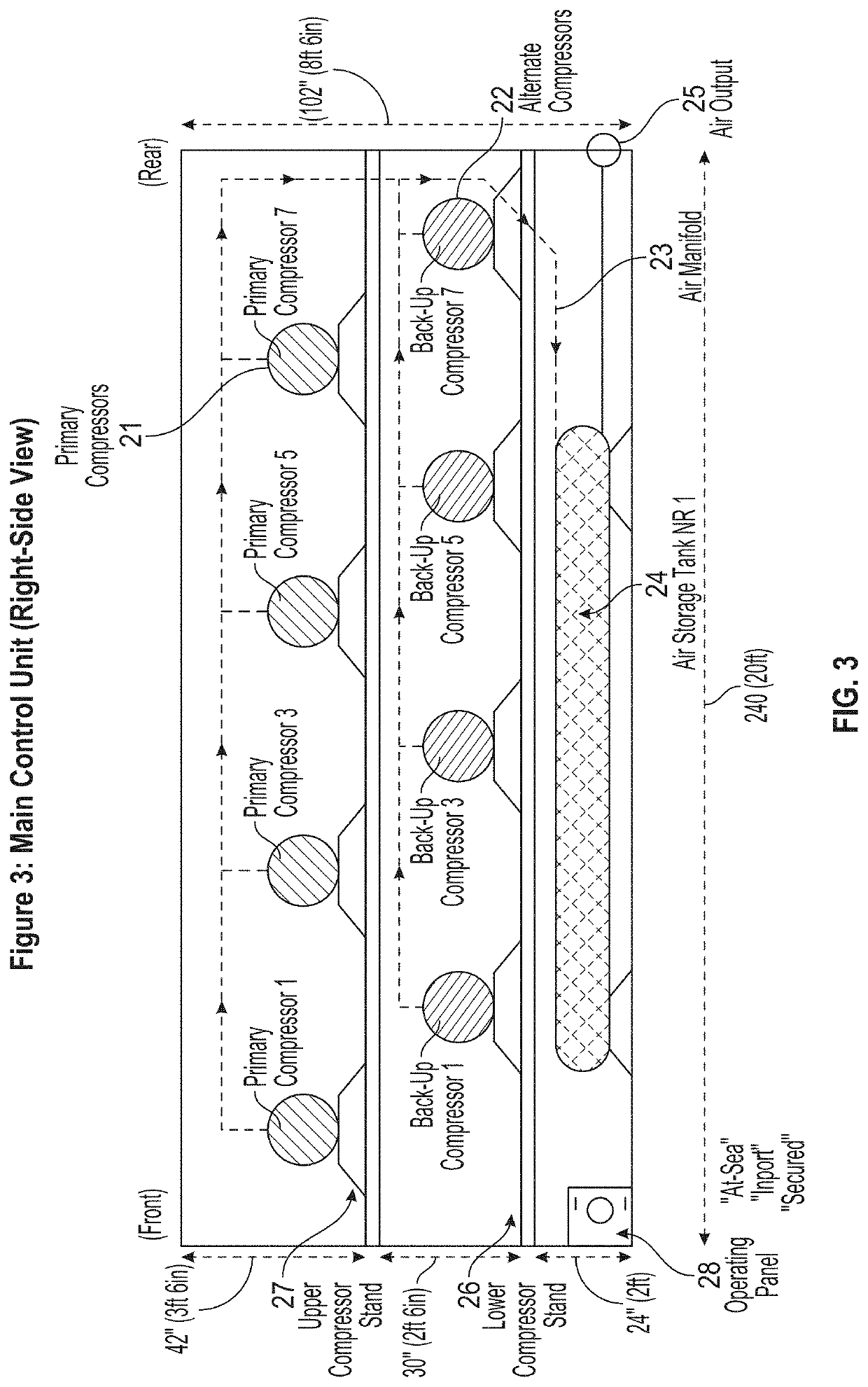
CROSS-REFERENCE TO RELATED APPLICATION[0001]This application claims the benefit of U.S. Provisional Application No. 63 / 136,147, filed on Jan. 11, 2021, the entire contents of which are incorporated herein by reference for all purposes.FIELD OF INVENTION[0002]The embodiments of the present disclosure relates generally to the field of facilitating a laminar flow and sound mitigation between a wetted hull of a vessel and surrounding fluid. More specifically, the present disclosure includes methods, systems, and apparatuses to facilitate providing and sustaining a laminar flow of a fluid across a vessel.BACKGROUND[0003]Existing techniques for facilitating providing and sustaining a laminar flow of a fluid across a vessel are deficient with regard to several aspects. For instance, current technologies do not reduce viscous resistance (RV) across a greater surface area but focus solely upon the flat-bottom portion of the wetted hull. Furthermore, current technologies do not facilitate ins...

Claims


Application Information

Patent Timeline
IPC IPC(8): B63B1/38
CPCB63B1/38B63B2001/387
Inventor PARKER, III, WILLIAM J.WORKMAN, HAROLD THOMASBRINSON, KATHERINE HOWELL
Owner PARKER MARITIME TECH LLC
Learn More