
Rolling diaphragm pump

Pending Publication Date: 2022-07-07
NIPPON PILLAR PACKING CO LTD
View PDF15 Cites 0 Cited by
  • Summary
  • Abstract
  • Description
  • Claims
  • Application Information

AI Technical Summary

Benefits of technology

The present invention helps prevent wrinkles in the rolling diaphragm without costing an arm and a leg.

Problems solved by technology

Since the rolling diaphragm made of a synthetic resin has poor followability to the reciprocation of the piston, wrinkles may occur at a portion other than the bent portion during the bending motion, and the rolling diaphragm may be torn.

Method used


Image

  • Rolling diaphragm pump
  • Rolling diaphragm pump
  • Rolling diaphragm pump

Examples


Embodiment Construction

[0022]Next, preferred embodiments of the present invention will be described with reference to the accompanying drawings.

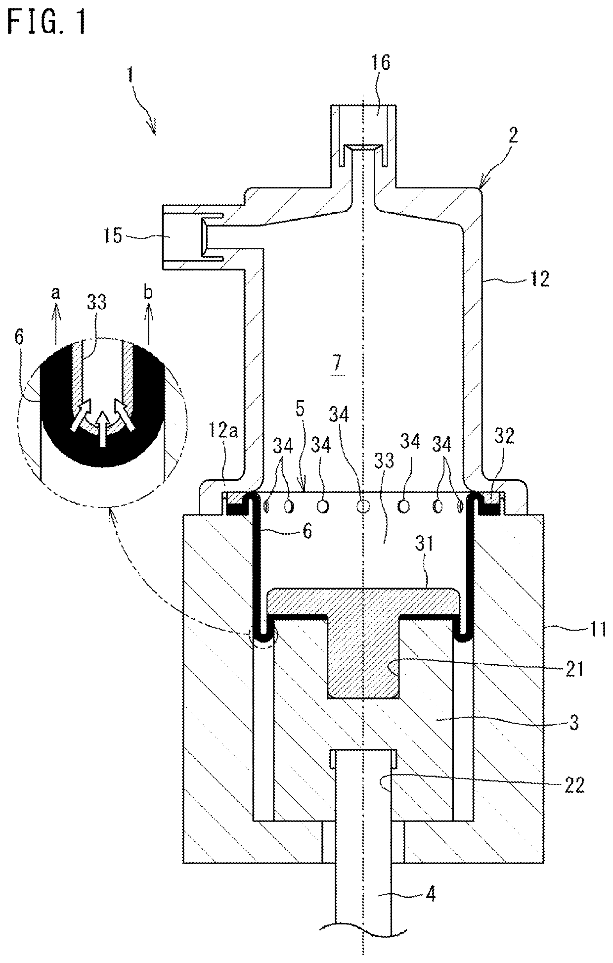
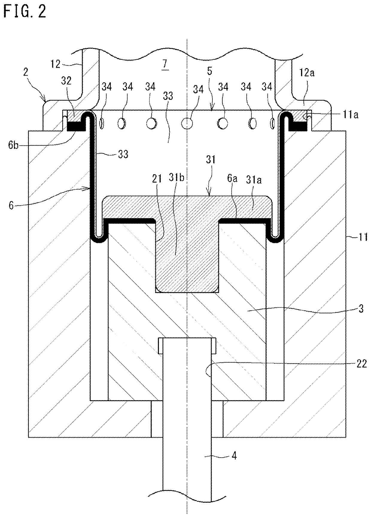
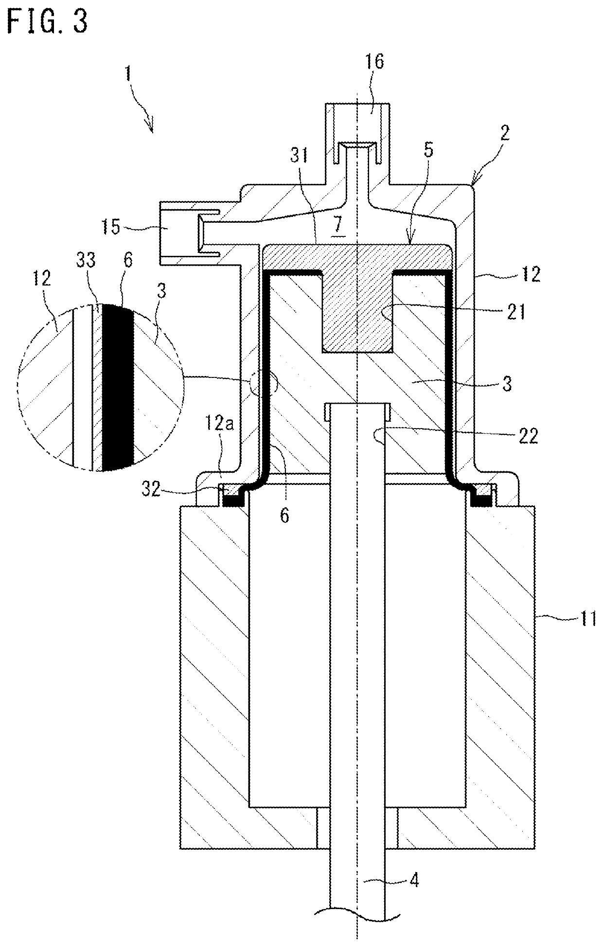
[0023]FIG. 1 is a cross-sectional view of a rolling diaphragm pump according to an embodiment of the present invention. The rolling diaphragm pump 1 includes a housing 2, a piston 3, a shaft 4, and a rolling diaphragm 5. In the present embodiment, the rolling diaphragm pump 1 (hereinafter, also referred to simply as pump 1) is placed such that the longitudinal direction (axial direction) thereof is the up-down direction, but may be placed such that the longitudinal direction (axial direction) thereof is a horizontal direction.

[0024][Configuration of Housing]

[0025]The housing 2 has a cylinder 11 and a pump head 12. The cylinder 11 is formed in a cylindrical shape, and is disposed such that the axial direction thereof coincides with the up-down direction. The pump head 12 is formed in a cylindrical shape with a lid, and is mounted on the upper side in the axial dire...


PUM


Abstract

A rolling diaphragm 5 of a rolling diaphragm pump 1 has a movable portion 31 reciprocatable together with a piston 3, a fixed portion 32 fixed to a housing 2, and a thin film portion 33 connecting the movable portion 31 and the fixed portion 32 and bending due to reciprocation of the piston 3. A rubber layer 6 is overlaid on the thin film portion 33 without being adhered to the thin film portion 33, an end portion 6a on the movable portion 31 side of the rubber layer 6 is fixed to the piston 3, and an end portion 6b on the fixed portion 32 side of the rubber layer 6 is fixed to the housing 2.

Description

TECHNICAL FIELD[0001]The present invention relates to a rolling diaphragm pump.BACKGROUND ART[0002]For example, in a production process for a semiconductor, a liquid crystal device, an organic EL device, a solar cell, etc., a rolling diaphragm pump having excellent chemical resistance is used as a pump for feeding a chemical solution when the chemical solution is applied or dispensed. In the rolling diaphragm pump, when a piston is reciprocated in a cylinder, a rolling diaphragm made of a synthetic resin makes a bending motion to change the volume of the interior of a pump chamber (pressure chamber), whereby the chemical solution is sucked into the pump chamber and discharged from the pump chamber.[0003]Since the rolling diaphragm made of a synthetic resin has poor followability to the reciprocation of the piston, wrinkles may occur at a portion other than the bent portion during the bending motion, and the rolling diaphragm may be torn.[0004]Therefore, in PATENT LITERATURE 1, the o...

Claims


Application Information

Patent Timeline
IPC IPC(8): F04B43/02F04B53/14
CPCF04B43/02F05B2210/11F04B53/14F04B43/0054F04B43/009
Inventor TESHIMA, KAZUKIYONOTOJI, YUHIGUCHI, SHINGO
Owner NIPPON PILLAR PACKING CO LTD
Learn More