
High-voltage junction box for an electrically driven vehicle and electrically driven vehicle

a high-voltage junction box and vehicle technology, applied in the direction of charging stations, electrical apparatus construction details, transportation and packaging, etc., can solve the problems of high tension applied to the connector, large gaps, and large tolerance of the contactor and other elements of the junction box, so as to achieve the effect of convenient replacemen

Pending Publication Date: 2022-06-23
VITESCO TECH GERMANY GMBH
View PDF4 Cites 0 Cited by
  • Summary
  • Abstract
  • Description
  • Claims
  • Application Information

AI Technical Summary

Benefits of technology

This patent is about a high-voltage junction box for electric vehicles that solves problems with previous junction boxes. The invention allows for easy replacement of components without damaging others. A tolerance compensation element is used to balance the size of the contactor with the housing, resulting in a fixed position of the contactor. The contactor is connected to the housing with two mounting ears and a metal bushing, and a heat conducing paste is used to effectively cool the bus bar. The invention also avoids the risk of detachment from the cooling surface and ensures efficient cooling of the bus bar.

Problems solved by technology

However, the tolerances of the contactor and other elements of the junction box, in particular of a connector and a bus bar, are comparatively large.
That may result in considerable gaps between e.g. the housing and the mounting surface of the contactor and therefore in high tensions applied to the connector.
While some of those tolerances may be balanced during the assembly, it is not always possible to compensate tolerances in the case of a repair.
The contactor is a rather vulnerable component, which might be replaced during the lifetime of the vehicle.
Those tolerances cannot be balanced without applying tension to the contactor, the bus bar and the connector.

Method used


Image

  • High-voltage junction box for an electrically driven vehicle and electrically driven vehicle

Examples


Embodiment Construction

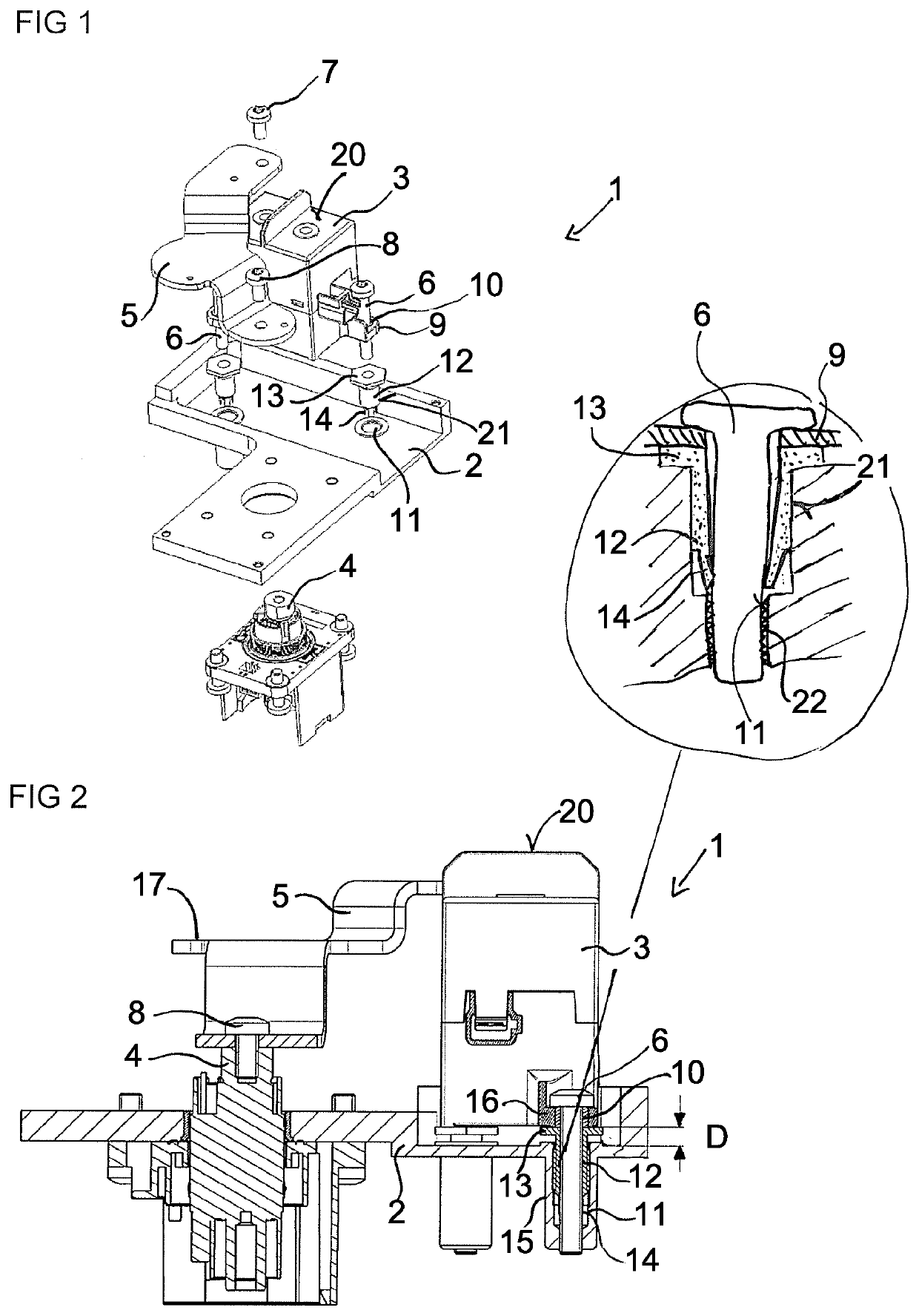
[0027]Referring now to the figures of the drawings in detail and first, particularly, to FIG. 1 thereof, there is seen a part of a high-voltage junction box 1 for an electrically driven vehicle. The junction box 1 includes a housing, of which a housing part 2 is shown. The junction box 1 further includes a contactor 3 for coupling an external power source to a vehicle battery and decoupling it in case of an overvoltage. The junction box 1 further includes a connector 4 for connection to a vehicle battery and a bus bar 5 for electrical connection of the contactor 3 and the connector 4. Typically, the junction box further includes a second bus bar which is not shown herein. Hence, the junction box 1 connects the vehicle battery to an external charging device, in which the contactor 3 is placed towards the external charging device and the connector 4 towards the battery.

[0028]The contactor 3 is fixed to the housing part 2 by two screws 6. The bus bar 5 is fixed to the contactor 3 by a ...


PUM


Abstract

A high-voltage junction box for an electrically driven vehicle includes a housing part with at least one mounting hole, a contactor mechanically connected to the housing part by at least one fastening element extending through a through hole in the contactor into the mounting hole, and a bus bar having a first contact area and a second contact area. The first contact area is electrically and mechanically connected to the contactor and the second contact area is electrically and mechanically connected to a connector. A tolerance compensation element suitable to compensate for tolerance variations in a distance or space between the housing part and the contactor is mounted in the at least one mounting hole. An electrically driven vehicle with a charging unit including a high-voltage junction box is also provided.

Description

CROSS-REFERENCE TO RELATED APPLICATION[0001]This application claims the priority, under 35 U.S.C. § 119, of European Patent Application EP20465601, filed Dec. 17, 2020; the prior application is herewith incorporated by reference in its entirety.FIELD AND BACKGROUND OF THE INVENTION[0002]The present invention relates to a high-voltage junction box for an electrically driven vehicle with a charging unit. The present invention further relates to an electrically driven vehicle including such a high-voltage junction box.[0003]High-voltage junction boxes usually connect an external power source to the vehicle battery in a charging event, in particular in a DC-charging event. They include a contactor, which might be a relay and which can couple and decouple the external power source and the vehicle battery. In case of an overvoltage, the contactor serves to disconnect the charger from the battery to prevent damage to electronic components.[0004]Typically, the contactor is fixed to a housin...

Claims


Application Information

Patent Timeline
Patent Type & Authority Applications(United States)
IPC IPC(8): H02G3/08H05K7/20H02G5/06
CPCH02G3/086H02G5/06H05K7/20854H01R9/18B60L53/22B60R16/0238H01R2201/26B60R16/02
Inventor ANDREI, SORINTRIF, EDUARD IOSIF
Owner VITESCO TECH GERMANY GMBH
Learn More