
Device and method for determining a focal position of laser beam

a laser beam and focal position technology, applied in the field of laser beam focal position determination devices and methods, can solve the problems of low level of measurement accuracy, inability to precisely determine, and loss of thermal lens information, and achieve the effect of compact and simple manner, minimal construction effor

Pending Publication Date: 2022-06-23
PRECITEC GMBH
View PDF0 Cites 0 Cited by
  • Summary
  • Abstract
  • Description
  • Claims
  • Application Information

AI Technical Summary

Benefits of technology

The invention is a device and method for accurately focusing a laser beam, in real-time, on a specific position. This device can be easily integrated into a laser machining head and requires minimal constructional effort. The technical effects include improved laser machining efficiency, reduced energy consumption, and improved part quality.

Problems solved by technology

If only a fraction of the laser beam is measured, information about the thermal lens is lost and it is not possible to precisely determine its influence on the focal position.
If the focal position is only determined with the information from the marginal rays, then only a low level of measurement accuracy is to be expected.
The thermal lens not only results in a focal shift, but also in deterioration of the beam quality due to imaging errors.
This results in a change in the entire beam caustic including the focus diameter.
The problem is the integration of these methods and devices into a laser machining head in order to ensure precise focal position measurement in real time during a laser material machining process.
Using methods and devices that enable focal position control without measuring the actual focal position, an improvement in the machining quality can be achieved with minimal constructional effort, but high precision in the focal position control and therefore also high machining quality cannot be achieved.
However, the larger the autofocus range, the more difficult it is to provide a simple and compact focal position measurement.

Method used


Image

  • Device and method for determining a focal position of laser beam
  • Device and method for determining a focal position of laser beam
  • Device and method for determining a focal position of laser beam

Examples


Embodiment Construction

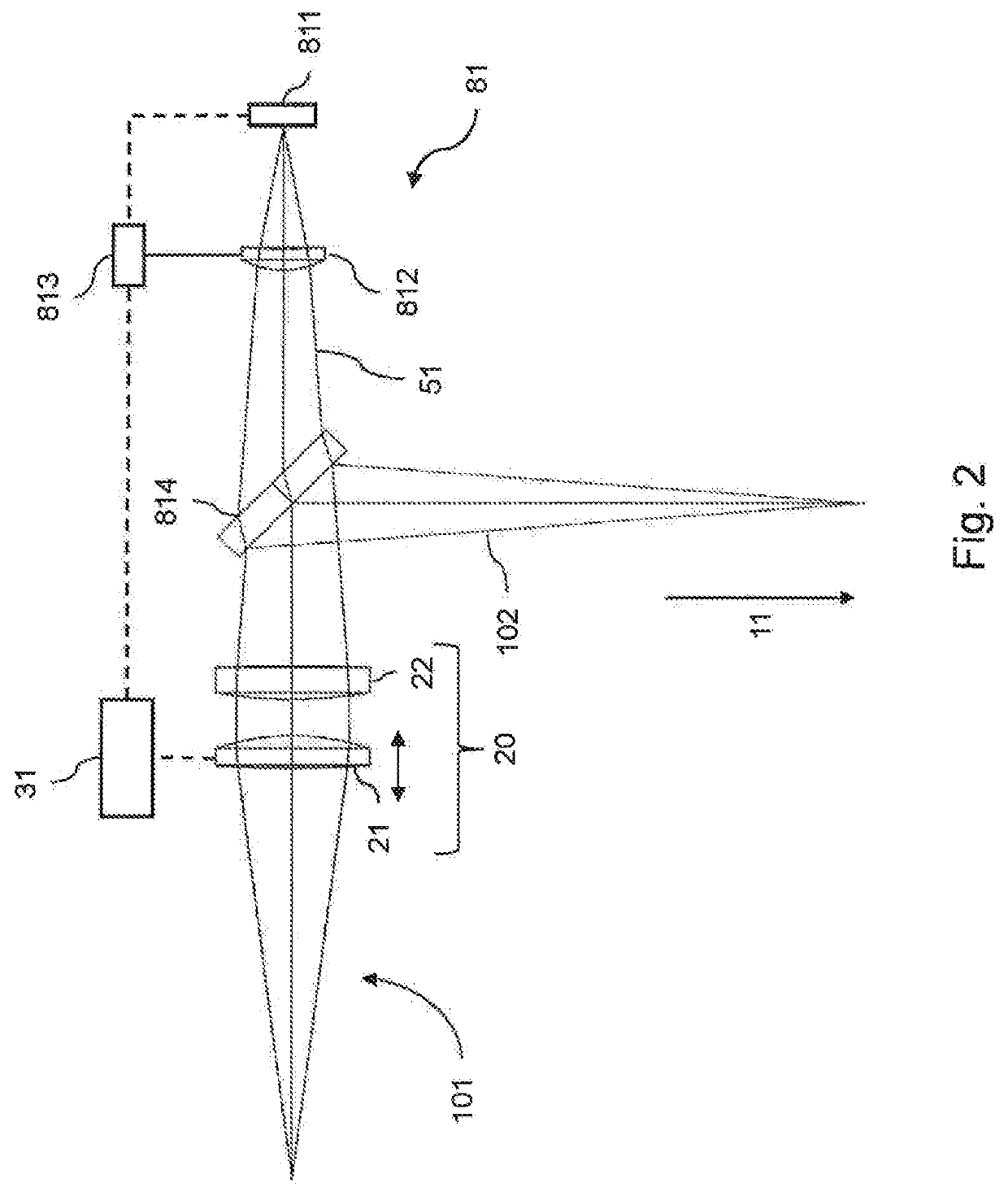
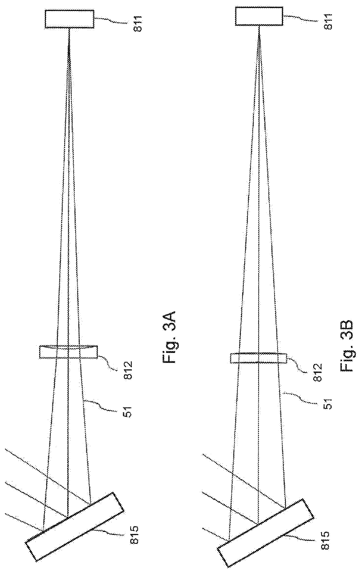
[0064]Unless otherwise noted, the same reference symbols are used in the following for elements that are the equivalent and have equivalent effect.

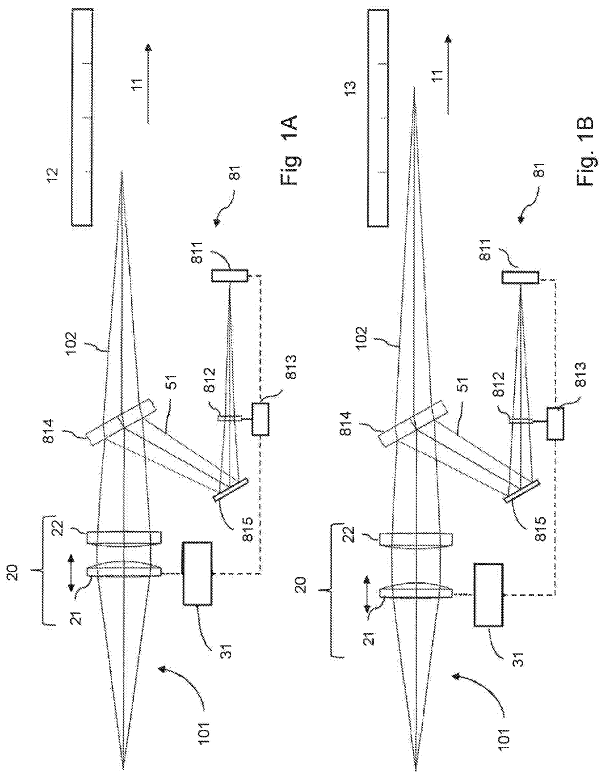
[0065]FIG. 1A is a schematic view of a device for determining a focal position of a machining laser beam of a laser machining head and a laser machining head according to an embodiment of the present invention.

[0066]The laser machining head 101 is configured to generate a machining laser beam 102. The machining laser 102 is radiated onto a workpiece (not shown) in order to machine the workpiece. The machining laser beam 102 has a direction of propagation 11. The direction of propagation 11 may be substantially perpendicular to a surface of the workpiece to be machined.

[0067]The laser machining head 101 comprises a focusing unit 20. The focusing unit 20 is configured to set the focal position of the machining laser 102. As shown in FIG. 1A, the machining laser 102 has a first focal position 12. The focusing unit 20 comprises an element 21 ...


PUM

PropertyMeasurementUnit
focal lengthaaaaaaaaaa

Abstract

A device for determining a focal position of a laser beam, in particular a processing laser beam in a laser processing head, has an optical decoupling element for decoupling a partial beam from a beam path of the laser beam, a detector for detecting at least one beam parameter of the partial beam, and at least one optical element with an adjustable focal length, which is arranged in a region of the beam path of the partial beam between the optical decoupling element and the detector. Also disclosed is a laser processing head which includes a device of this type, as well as a method for determining a focal position of a laser beam.

Description

CROSS-REFERENCE TO RELATED APPLICATIONS[0001]This application is the U.S. National Stage of PCT / EP2020 / 055416 filed Mar. 2, 2020, which claims priority to Germany Application No. 102019109795.9, filed Apr. 12, 2019, the entire content of both are incorporated herein by reference in their entirety.BACKGROUND OF THE INVENTION[0002]The present invention relates to a device for determining a focal position of a laser beam, in particular a machining laser beam in a laser machining head, and a method for determining a focal position of a laser beam. The invention also relates to a laser machining head comprising such a device. Such devices and methods may be used to determine and control the focal position in a laser machining head during laser material machining.FIELD OF THE INVENTION[0003]A problem in laser material machining is the so-called “thermal lens” (thermally induced change in refractive power) which is a result of the heating of optical elements for guiding and focusing the la...

Claims


Application Information

Patent Timeline
Patent Type & Authority Applications(United States)
IPC IPC(8): G01J1/04G02B26/08G01J1/42B23K26/046B23K26/70
CPCG01J1/0411G02B26/08B23K26/705B23K26/046G01J1/4257G02B27/40G01J1/42B23K26/04G01J1/04G02B27/16B23K26/702G01J1/0407G01J1/0414G01J2001/4261
Inventor BLÁZQUEZ SÁNCHEZ, DAVID
Owner PRECITEC GMBH
Learn More