Eureka AIR delivers breakthrough ideas for toughest innovation challenges, trusted by R&D personnel around the world.

Headphone

a headphone and microphone technology, applied in the field of headphone, can solve the problems of inconvenient use and the size of the headphone, and achieve the effects of reducing the internal space of the base occupied by the signal cable, preventing abnormal noise, and reducing the manufacturing cost of the headphon

Active Publication Date: 2022-06-16
CHENG UEI PRECISION IND CO LTD
View PDF7 Cites 0 Cited by
  • Summary
  • Abstract
  • Description
  • Claims
  • Application Information

AI Technical Summary

Benefits of technology

The patent is about a new headphone design that reduces manufacturing costs and volume while improving sound quality. The design includes a signal cable that is soldered to a circuit board to prevent abnormal noises and a microphone assembly that is housed in a space surrounded by a first convex part and the circuit board. This design also includes an enclosure that prevents dust and debris from affecting the signal cable. The headphone also has a locating space for a protruding portion of an enclosure and a circle wall of a cable reel limited in a limiting slot of the enclosure. These features improve the sound quality and volume of the headphone.

Problems solved by technology

However, when users use the headphones, internal signal cables are discovered to be coiled in the headphones, and the internal signal cables will contact with devices in a sound chamber to produce abnormal noises, so inconveniences are caused to the users.
However, the above-mentioned connecting cable is coiled in the housing, and the connecting cable still occupies an internal space, so the connecting cable is still easy to contact with the devices in the sound chamber to produce the abnormal noises and only reduce a volume of the bracket, and the conventional headphone is still in a larger size.

Method used


Image

  • Headphone
  • Headphone
  • Headphone

Examples


Embodiment Construction

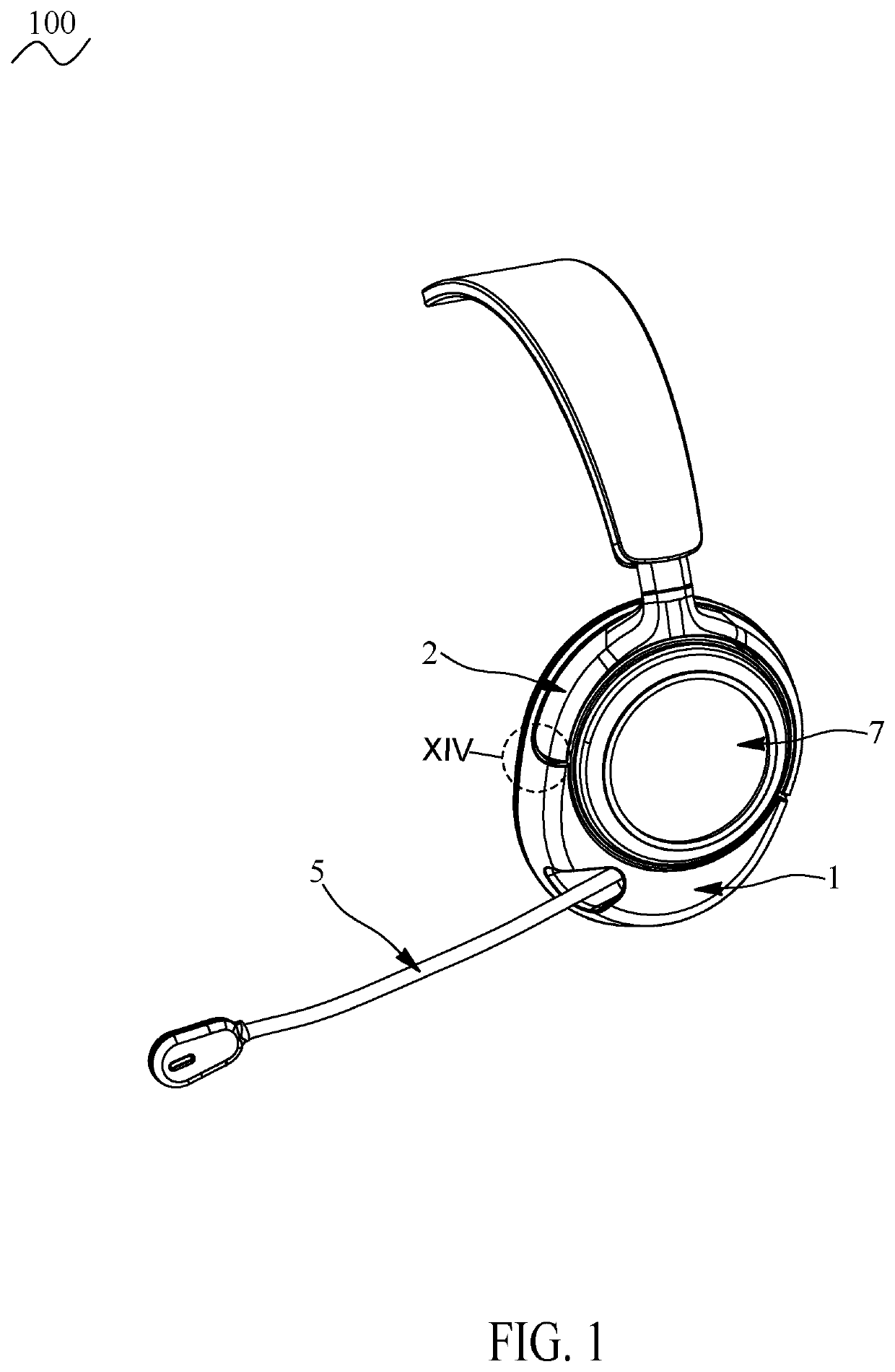
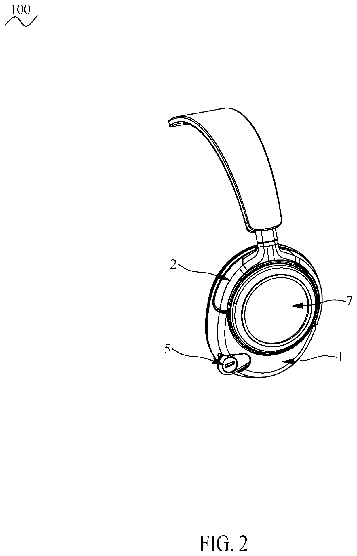
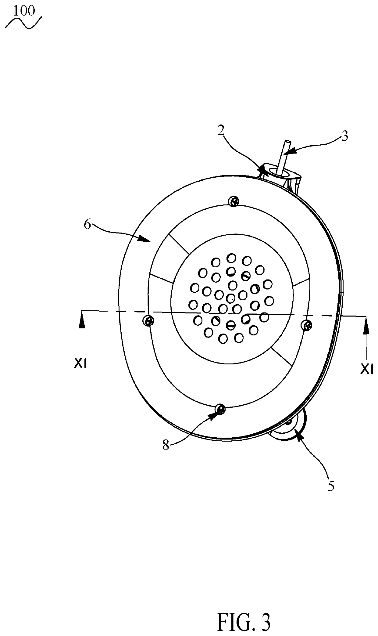
[0026]Referring to FIG. 1 to FIG. 12, a headphone 100 in accordance with a preferred embodiment of the present invention is shown. The headphone 100 includes a base 1, a bracket 2, a signal cable 3, a circuit board 4, a microphone assembly 5, a sound chamber unit 6 and a decorative cover 7.

[0027]The bracket 2 is mounted to a top of the base 1. One end of the signal cable 3 passes through an upper portion of the bracket 2, and the one end of the signal cable 3 further passes through the bracket 2. The signal cable 3 is disposed along an inside of the bracket 2 and the one end of the signal cable 3 passes through a lower end of the bracket 2 and enters the base 1 through the lower end of the bracket 2. The one end of the signal cable 3 is soldered to one end of the circuit board 4. The circuit board 4 is mounted in the base 1. The microphone assembly 5 is mounted in the base 1. The microphone assembly 5 is located at one side of the circuit board 4. The headphone 100 is arranged with ...


PUM


Abstract

A headphone includes a base, an accommodating space, a bracket, a circuit board accommodated in the accommodating space, a signal cable, a microphone assembly accommodated in the accommodating space, and a sound chamber unit accommodated in the accommodating space. The base has a sidewall and an outer wall surrounding the accommodating space. A junction portion between the sidewall and the outer wall is recessed inward to form a recess. At least one connection wall has a through hole communicated with the accommodating space. The bracket is received in the recess. The bracket includes an outer cover and an inner cover. A cable path is formed between the outer cover and the inner cover. One end of the bracket has a guiding slot connected to the cable path. The guiding slot is corresponding to the through hole. The signal cable is arranged along the cable path.

Description

CROSS-REFERENCE TO RELATED APPLICATION[0001]The present application is based on, and claims priority from, China Patent Application No. 202023022395.5, filed Dec. 16, 2020, the disclosure of which is hereby incorporated by reference herein in its entirety.BACKGROUND OF THE INVENTION1. Field of the Invention[0002]The present invention generally relates to a headphone, and more particularly to a headphone having a cable arrangement structure.2. The Related Art[0003]Generally, current earphones are various types. The current earphones include earbuds, in-ear earphones, headphones, etc. Compare the headphone with other earphones, and the headphone is able to cover a user's ear completely to make the headphone more comfortable to be worn. However, when users use the headphones, internal signal cables are discovered to be coiled in the headphones, and the internal signal cables will contact with devices in a sound chamber to produce abnormal noises, so inconveniences are caused to the use...

Claims


Application Information

Patent Timeline
Patent Type & Authority Applications(United States)
IPC IPC(8): H04R1/10H04R1/08
CPCH04R1/1033H04R1/1008H04R2201/107H04R1/1075H04R1/08H04R1/105
Inventor TSENG, CHI-MINGLIN, CHIN-CHUNG
Owner CHENG UEI PRECISION IND CO LTD
Why Eureka
Eureka Blog
Learn More