
Bone cement mixing assembly

a bone cement and mixing technology, applied in the field of medical use mixing equipment, can solve the problems of increasing the cost of bone cement preparation, and affecting so as to improve the recovery rate of high-viscosity bone cement, reduce the time of the transfer process, and accelerate the effect of bone cement preparation speed and efficiency

Active Publication Date: 2022-06-09
XELITE BIOMED LTD
View PDF3 Cites 2 Cited by
  • Summary
  • Abstract
  • Description
  • Claims
  • Application Information

AI Technical Summary

Benefits of technology

The present invention is a bone cement mixing assembly that can quickly and efficiently prepare bone cement. Its unique design allows for quick collection and transfer of bone cement from the stirring barrel to the syringe barrel, improving the recovery rate of high-viscosity bone cement and reducing the time of the transfer process. Overall, this assembly provides an efficient and reliable tool for orthopedic surgery.

Problems solved by technology

Therefore, if the injected amount is not appropriate during the operation, it is easy to cause the bone cement to leak out from the cracks of the bone, and then damage the surrounding nerves, muscles or cartilage tissues, which causes patient's discomfort and sequelae after the surgery.
These new bone cements have high viscosity and low fluidity, which reduces the leakage problem during the operation, thus greatly improving the safety of the operation, but the price is much more expensive.
However, the mixing process of high-viscosity bone cement is not only quite laborious, but also agglomerates this high-viscosity bone cement into many clumps of different sizes after mixing, which need to be collected one by one and transferred into a syringe before surgery use.
If the recovery rate of the mixed bone cement is too low, it will undoubtedly cause unnecessary waste.
But it will take too much time if the mixed bone cement is collected carefully, which will likely cause the bone cement to solidify and become unusable during the collection period.
Therefore, how to quickly and efficiently prepare this high-viscosity bone cement is an urgent problem to be solved in practice.

Method used


Image

  • Bone cement mixing assembly
  • Bone cement mixing assembly
  • Bone cement mixing assembly

Examples


Embodiment Construction

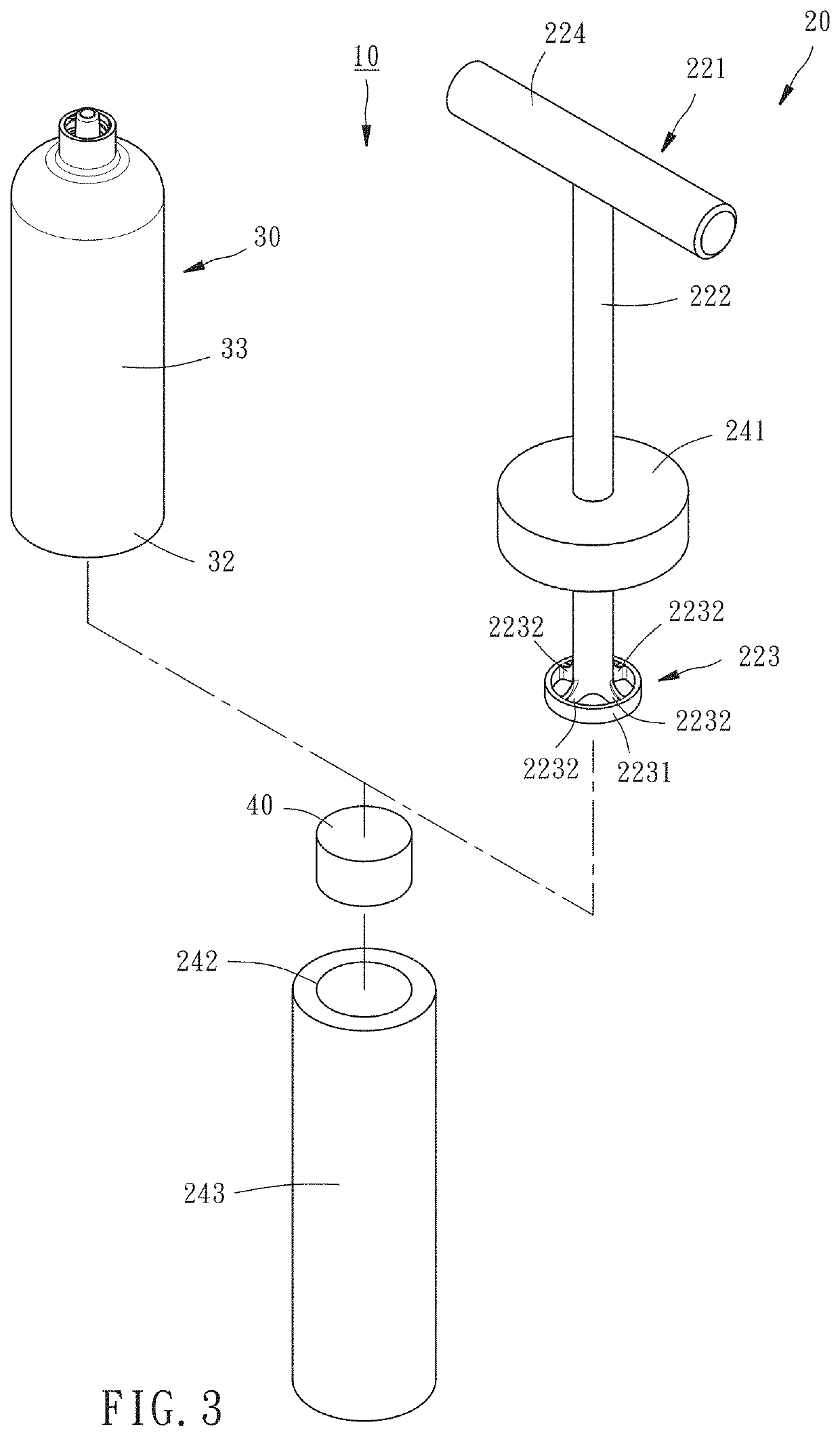
[0027]Please refer to FIGS. 1-6, the bone cement mixing assembly 10 provided by an embodiment of the present invention comprises a mixer 20, a syringe barrel 30 and a movable plug cover 40.

[0028]As shown in FIGS. 1, 3 and 4, the mixer 20 comprises a stirring rod 22 and a stirring barrel 24. The stirring rod 22 has a holding end 221, a rod body 222 and a stirring end 223. The stirring barrel 24 has a barrel cover 241, a first barrel open 242, a first barrel body 243, a first barrel bottom 244 and a stirring space 245. The barrel cover 241 is detachably sleeved on the first barrel open 242. The stirring end 223 movably passes through the barrel cover 241. The stirring space 245 is located in the first barrel body 243. The first barrel bottom 244 has a opening 246.

[0029]In this embodiment, as shown in FIGS. 3 and 4, the holding end 221 further having a grip 224, and the grip 224 and the rod body 222 which forms a T-shape for grasping to mix the bone cement by the user. Moreover, the fi...


PUM

PropertyMeasurementUnit
Diameteraaaaaaaaaa
Radiusaaaaaaaaaa
Transparencyaaaaaaaaaa

Abstract

The invention provides a bone cement mixing assembly including a mixer, a syringe barrel and a movable plug cover. The mixer includes a stirring rod and a stirring barrel. The stirring rod has holding end, a rod body and a stirring end. The stirring barrel has a barrel cover, a first barrel open, a first barrel body, a first barrel bottom, and a stirring space located in the first barrel body. The syringe barrel has a second barrel open, a second barrel body, a second barrel bottom, and an injection space located in the second barrel body. In this way, the complete-stirred bone cement in the stirring barrel can be directly collected and pushed into the syringe barrel through the movement of the movable plug cover to achieve the effect of completing the preparation of the bone cement quickly and efficiently.

Description

BACKGROUND OF THE INVENTION1. Field of the Invention[0001]The present invention relates to a mixing equipment for medical use, in particular to a bone cement mixing assembly2. Description of the Related Art[0002]Bone cement is a kind of medical material for orthopedic filling use with polymethylmethacrylate (PMMA) as the main ingredient. It is mostly used to fill cavities form tooth decay, artificial joint replacement surgery, cementation vertebroplasty surgery and other orthopedic surgery for filling or bonding purposes.[0003]Traditional bone cement has low viscosity and high fluidity. Therefore, if the injected amount is not appropriate during the operation, it is easy to cause the bone cement to leak out from the cracks of the bone, and then damage the surrounding nerves, muscles or cartilage tissues, which causes patient's discomfort and sequelae after the surgery. In order to solve such problems, many manufacturers have recently developed new bone cements. These new bone cement...

Claims


Application Information

Patent Timeline
IPC IPC(8): A61B17/88B01F33/501B01F23/53B01F35/32A61B17/00B01F101/20
CPCA61B17/8833B01F33/50112B01F23/53B01F2101/20A61B2017/00477A61B2017/00902A61B2017/8838B01F35/3202A61B17/8825B01F35/754251B01F31/441B01F31/40
Inventor CHEN, HSIU-CHUANKAO, CHUNG-WEILIANG, YUNG-HEYU, CHIH-TAI
Owner XELITE BIOMED LTD
Learn More