System for supplying energy to electrically operated mining machines

a mining machine and electrical technology, applied in the direction of photovoltaic energy generation, single network parallel feeding arrangement, ac network load balancing, etc., can solve the problems of high fuel consumption and negative cosub>2, and achieve the effect of reducing emissions and saving space and resources

Pending Publication Date: 2022-06-02
LIEBHERR MINING EQUIP COLMAR
View PDF0 Cites 0 Cited by
  • Summary
  • Abstract
  • Description
  • Claims
  • Application Information

AI Technical Summary

Benefits of technology

The patent aims to reduce the use of fossil fuels in mining machines to improve economic and ecological effects. This is achieved through the use of a hybrid power generator, which helps to reduce emissions. Additionally, the patent suggests using hydrogen generated by a hydrogen generation unit and stored, instead of conducting it to the fuel cell. This hydrogen can also be used by a hydrogen-assisted dual fuel diesel engine.

Problems solved by technology

It is therefore clear that the use of fossil energy carriers for power generation results in a high fuel consumption and leaves a negative CO2 balance.
Even though many attempts have been made, no serious measures have been taken to date to considerably reduce the emissions in the mines that operate fleets of electrically driven mining machines.
Such mining machines are typically connected to non-renewable energy sources so that their ecological effects are negative due to the consumption of a large amount of fossil fuels.
The energy from the energy store or from the fuel cell can thus be used for the operation of the mining machines and the internal combustion engine generator can only be made use of when the capacity of the other energy sources cannot meet the power requirement of the mining machines.
A suddenly required peak load can, however, naturally also have the result that the hybrid power generation arrangement generates power and provides it to the mining machines.

Method used


Image

  • System for supplying energy to electrically operated mining machines
  • System for supplying energy to electrically operated mining machines
  • System for supplying energy to electrically operated mining machines

Examples


Embodiment Construction

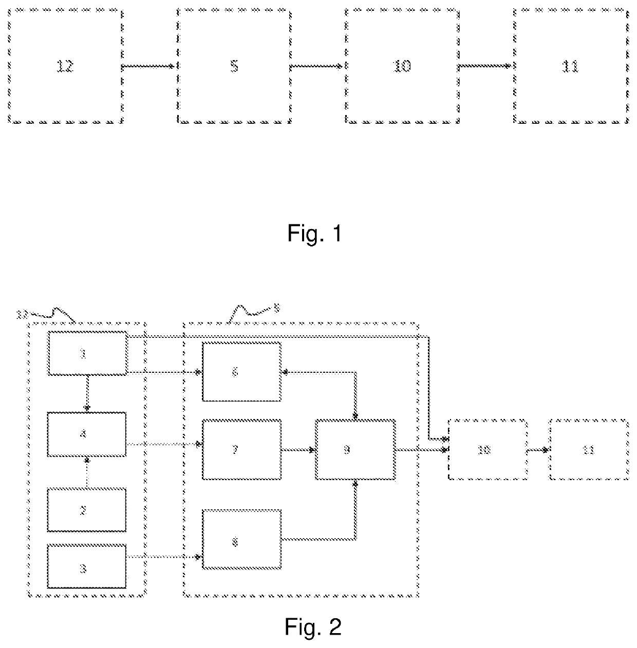
[0040]FIG. 1 shows the main basic components that are provided for the energy supply of the electrically driven mining machines 11 in accordance with the disclosure.

[0041]Starting from the at least one energy source 12, the hybrid power generation arrangement 5 is supplied. The power generated herein or the forwarded power is then passed on via the cable routing system 10 to the electrically driven mining machines 11 where the power is converted into mechanical work. As shown in detail later, the at least one energy source 12 can supply the electrically driven mining machines 11 with power both directly and via the hybrid power generation arrangement.

[0042]FIG. 2 shows the at least one energy source 12 and the hybrid power generation arrangement 5 in a representation richer in detail.

[0043]The at least one energy source 12 here includes an electricity plant and / or a connection to a power supply network 1, a hydrogen generation unit 4 for producing and storing hydrogen, and a fuel re...


PUM


Abstract

A system for supplying energy to electrically operated mining machines, which system includes a hybrid power-generation arrangement for outputting electricity for the mining machines, a cable routing system for routing at least one power cable from the hybrid power-generation arrangement to the mining machines, and at least one energy source for supplying energy to the hybrid power-generation arrangement, wherein the hybrid power-generation arrangement has an electrochemical energy store, a fuel cell and an internal combustion engine generator.

Description

TECHNICAL FIELD[0001]The present disclosure relates to a system for supplying energy to electrically operated mining machines. The mining machines are typically used in surface mining or in a mine.BACKGROUND AND SUMMARY[0002]Electrically driven mining machines require large and constant amounts of energy to perform their work, exactly like their diesel-operated counterparts. The amount of energy required for a medium-sized electrically driven hydraulic excavator amounts to multiple tens of megawatt hours per day.[0003]It is therefore clear that the use of fossil energy carriers for power generation results in a high fuel consumption and leaves a negative CO2 balance. Even though many attempts have been made, no serious measures have been taken to date to considerably reduce the emissions in the mines that operate fleets of electrically driven mining machines.[0004]Such mining machines are typically connected to non-renewable energy sources so that their ecological effects are negati...

Claims


Application Information

Patent Timeline
Patent Type & Authority Applications(United States)
IPC IPC(8): H02J15/00H02J3/28H02J3/38
CPCH02J15/008H02J3/28H02J3/381F03D9/19H02J2300/28H02J2300/40H02J2300/24H02J3/48H02J7/34Y02E60/36Y02E10/56Y02E10/76
Inventor KAREEMULLA, TARIQGLINIORZ, VOLKERRICHTHAMMER, BURKHARD
Owner LIEBHERR MINING EQUIP COLMAR
Why Eureka
Try Eureka