Imaging mass spectrometer

Pending Publication Date: 2022-06-02
SHIMADZU CORP
View PDF0 Cites 0 Cited by
  • Summary
  • Abstract
  • Description
  • Claims
  • Application Information

AI Technical Summary

Benefits of technology

The present invention provides an imaging mass spectrometer that can create a distribution image for a target component by using signal strengths of multiple kinds of product ions with different mass-to-charge ratios. This helps to eliminate the influence of other components and obtain a highly accurate MS image for the target component based on the user's intention.

Problems solved by technology

Components having sufficiently different mass-to-charge ratios can be separated from each other in mass spectrometry, but particularly in the case of a sample derived from a living body, many of the different components have the same or close masses, and are often not sufficiently separated in mass spectrometry.
Therefore, even if an MS image is created using a signal strength at a certain mass-to-charge ratio (m / z) value, there is a case where an MS image of another mass-to-charge ratio value within an allowable range of the mass-to-charge ratio value or an MS image of another component having the same mass-to-charge ratio is overlapped, and there is a problem that it is difficult to accurately grasp the two-dimensional distribution of the target component.

Method used


Image

  • Imaging mass spectrometer
  • Imaging mass spectrometer
  • Imaging mass spectrometer

Examples


Embodiment Construction

[0020]Hereinafter, one embodiment of an imaging mass spectrometer according to the present invention will be described with reference to the accompanying drawings.

[0021][Configuration of Device of Present Embodiment]

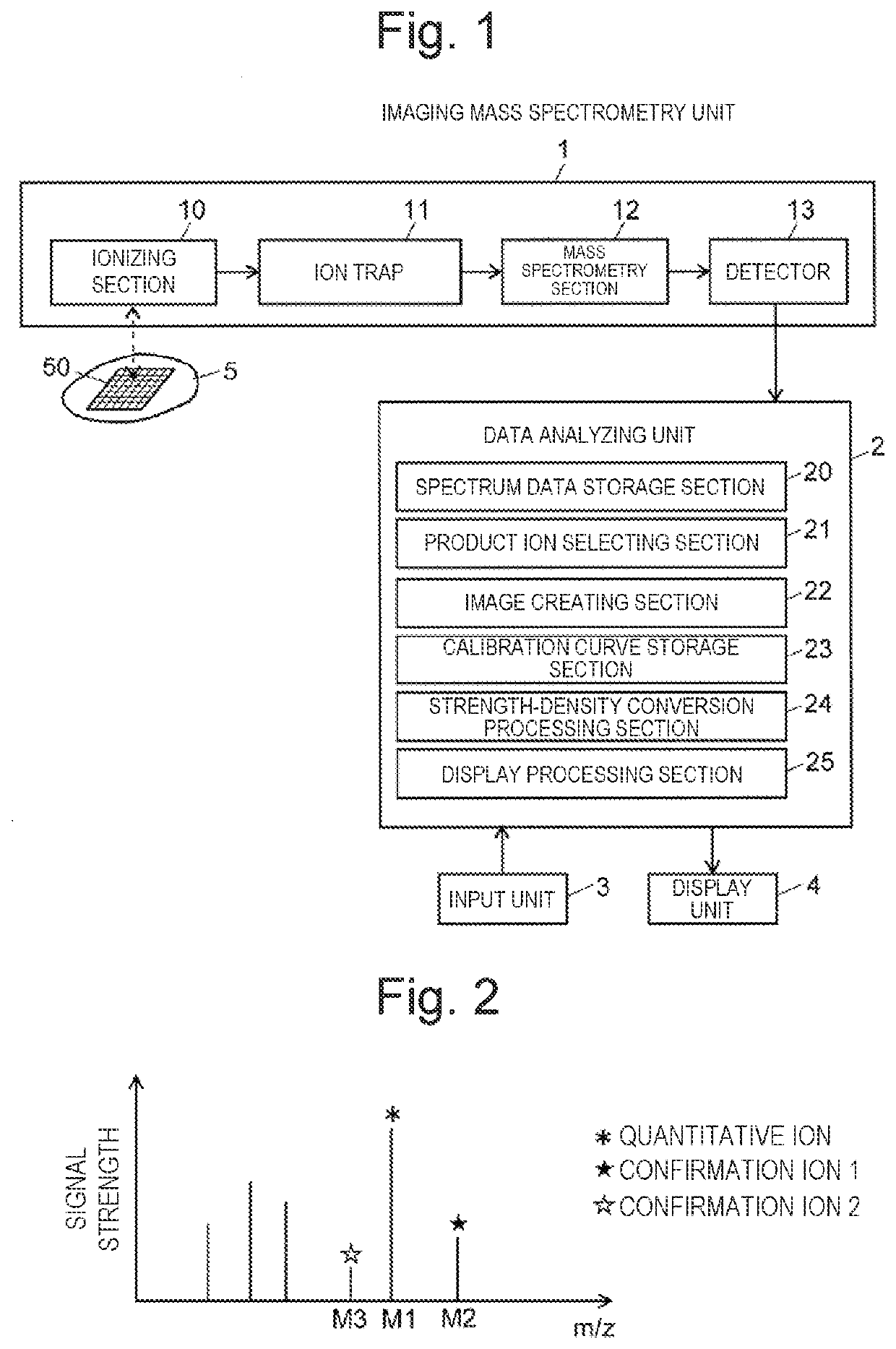
[0022]FIG. 1 is a schematic block configuration diagram of an imaging mass spectrometer of the present embodiment.

[0023]The imaging mass spectrometer of the present embodiment includes an imaging mass spectrometry unit 1, a data analyzing unit 2, an input unit 3, and a display unit 4.

[0024]The imaging mass spectrometry unit 1 executes imaging mass spectrometry on a sample and is capable of performing MSn analysis, where n is greater than or equal to 2. That is, the imaging mass spectrometry unit 1 includes an ionizing section 10, an ion trap 11, a mass spectrometry section 12, and a detector 13.

[0025]The ionizing section 10 is, for example, an ion source by an atmospheric pressure matrix-assisted laser desorption / ionization (AP-MALDI) method that irradiates a sample with...


PUM


Abstract

An imaging mass spectrometer includes an analysis executing section that executes MSn analysis for a target component on each of a plurality of micro regions set within a two-dimensional measurement region on a sample to collect data; an ion selecting section that selects a plurality of kinds of product ions derived from, or assumed to be derived from, the target component based on at least a part of the data collected by the analysis executing section; and a distribution image creating section that determines, using signal strength of each of the kinds of product ions in each micro region within the measurement region. a small region in which all of the kinds of product ions are detected or a small region assumed to have high reliability that all of the kinds of product ions are derived from the target component, and creates a distribution image visualizing the small region.

Description

TECHNICAL FIELD[0001]The present invention relates to an imaging mass spectrometer configured to execute mass spectrometry for each of a large number of measurement points (micro regions) within a two-dimensional region on a sample or within a three-dimensional region in a sample.BACKGROUND ART[0002]In the imaging mass spectrometer, a two-dimensional intensity distribution of ions having a specific mass-to-charge ratio m / z on the surface of a sample such as a biological tissue section can be measured while observing the form of the surface of the sample with an optical microscope (see Patent Literature 1 etc.). In the imaging mass spectrometer, a mass spectrometry image (hereinafter, sometimes referred to as an MS image), which shows a two-dimensional intensity distribution of ions at various mass-to-charge ratios, can be created for one sample.[0003]In a general imaging mass spectrometer, a matrix-assisted laser desorption / ionization (MALDI) method is used as an ionization method, ...

Claims


Application Information

Patent Timeline
IPC IPC(8): H01J49/00
CPCH01J49/0004H01J49/0036
Inventor YAMAGUCHI, SHINICHI
Owner SHIMADZU CORP
Why Eureka
Try Eureka