Programmatically determining next-hop mac address

a programmatic and mac address technology, applied in the direction of digital transmission, data switching network, electrical apparatus, etc., can solve the problems of reducing data upload and/or download rate, large volume content, and inability to programmatically determine the destination mac address via software implementations

Active Publication Date: 2022-05-12
KRATOS INTEGRAL HLDG LLC
View PDF4 Cites 0 Cited by
  • Summary
  • Abstract
  • Description
  • Claims
  • Application Information

AI Technical Summary

Benefits of technology

[0019]In addition, wherein the application has control over a NIC, such methods can further instruct the NIC to drop the phantom UDP. Such methods can further bypass the kernel and provide a next UDP to the NIC with the stored the next-hop MAC address header populated in the next UDP.

Problems solved by technology

The network may experience a variety of issues that impact data exchange rates (e.g., upload and / or download speeds) to the network.
These issues include large volume content requests that take time to populate each protocol header or otherwise diminish data upload rates and / or download rates.
However, a challenge arises, because in order to participate in a layer 2 / 3 switched network, there are many networking protocols, request for comments (RFCs), and standards that the application is required to implement in order to properly populate the layer 2 and 3 protocol headers.
However, there is no way to programmatically determine via software implementations the destination MAC address, as that is done in switched and routed networks, without re-implementing the networking stack functions for each packet (and thus re-invent the wheel each time).
In other words, there isn't a way to integrate the KNI / virtual interface and the networking-stack bypass through any sort of networking stack API call.
Even if such an API does exist in an operating system (as it does in Windows®), the API does not address whether an ARP should be solicited, as there could be various network-rules, security, or firewall measures that may have been put in place by a Network / System Administrator that would result in a differing response.

Method used


Image

  • Programmatically determining next-hop mac address
  • Programmatically determining next-hop mac address
  • Programmatically determining next-hop mac address

Examples


Embodiment Construction

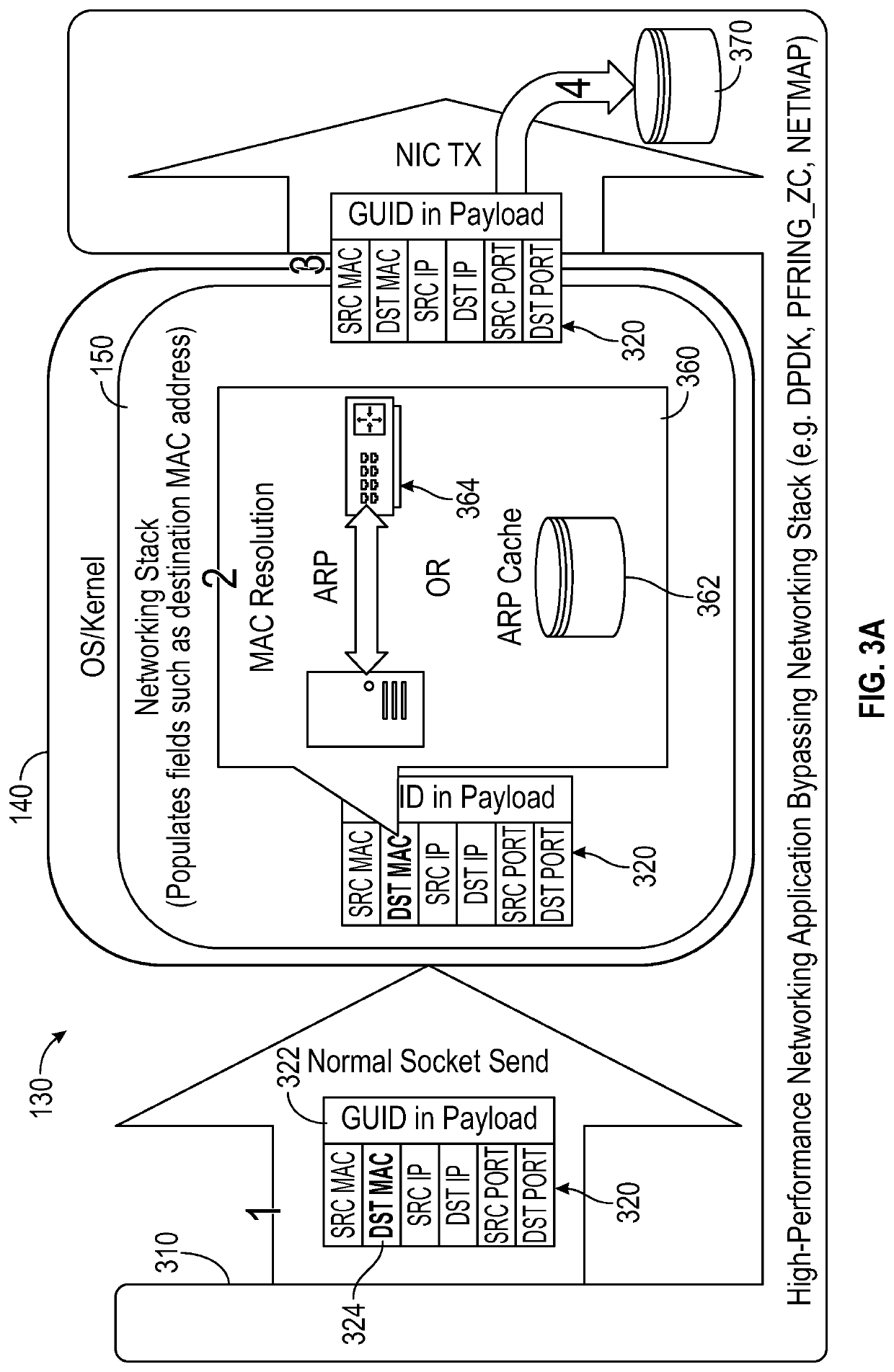
[0029]FIGS. 3A and 3B illustrate a schematic functional flow diagram of a network acceleration application 310 that is configured to determine a layer 2 DST address in accordance with the embodiments disclosed herein. Similar to FIG. 2, FIG. 3 illustrates an application 310 and networking stack 130 contained in an operating system. The networking stack 130 may be substantively similar to the networking stack 130 of FIG. 1. The application 310 may be similar to the application 210 of FIG. 2, in that application 310 resides at the application layer of the networking stack 130 and is configured to directly control the NIC for accelerated data packet exchange (the NIC is illustratively shown within the application 310). Thus, as with application 210, application 310 is able to bypass the kernel 140 and the layers of the networking stack implemented thereby for direct transmission of data packets.

[0030]The application 310 is also configured to determine a layer 2 DST address for use in t...


PUM


Abstract

Systems, media, and methods are capable of determining a layer 2 destination address that can then be used by a network acceleration application to populate data packets to be transmitted using accelerated networking techniques. The systems and methods provide for a software application executed on a computing device that controls a NIC interface to provide for an accelerated network. The software application resides in the application layer of a networking stack and is interfaced via a virtual NIC or TUN/TAP device with the kernel and the networking stack and operating system (OS) facilities to determine a layer 2 destination address for use in accelerated network applications. Embodiments herein, through the combination above, are able to account for firewall rules, static ARP entries, or any other system-administrator rules put in place for network operations.

Description

RELATED APPLICATIONS[0001]This application claims priority to U.S. Provisional Patent Application No. 63 / 111,487, filed on Nov. 9, 2020, which is hereby incorporated herein by reference as if set forth in full.FIELD OF THE INVENTION[0002]This application generally relates to routing data packets over a network and to routing such packets in an accelerated manner.BACKGROUND OF THE INVENTION[0003]In a typical network environment, client devices request and download content stored within network servers. The request is directed to the network servers using routers, gateways, and other network infrastructure devices that direct the requests through the network to the network servers as packets. Upon receiving the content requests, the network servers typically retrieve the requested content, break the requested content into packets, and transmit the packets to the requesting client device. Routers, gateways, and other network infrastructure direct these packets through the network to th...

Claims


Application Information

Patent Timeline
Patent Type & Authority Applications(United States)
IPC IPC(8): H04L29/12H04L12/741H04L29/06
CPCH04L61/6022H04L69/16H04L61/20H04L45/74H04L69/22H04L2101/622H04L61/50
Inventor BLACK, GABRIEL
Owner KRATOS INTEGRAL HLDG LLC
Why Eureka
Try Eureka