
Macro alignment reticle sight system

a reticle and macro alignment technology, applied in the field of aiming devices, can solve the problems of not being able to see the dot on the lens, unable to achieve this alignment, and only visible superimposed dots,

Active Publication Date: 2022-05-12
GRACE ENG
View PDF3 Cites 0 Cited by
  • Summary
  • Abstract
  • Description
  • Claims
  • Application Information

AI Technical Summary

Benefits of technology

This solution enhances target acquisition by providing rapid and efficient visual feedback, reducing frustration and improving alignment speed, even for inexperienced users, thereby enhancing shooting accuracy and safety.

Problems solved by technology

An issue with many reflex sights, in particular smaller ones, such as those used on handguns, is that the superimposed dot is only visible when the sight and lens are at a particular orientation relative to a use in a user's field of view.
For newer users, achieving this alignment can be difficult to do, particularly if the user is attempting to quickly align the sight on a target.
Due to the orientation of the firearm and sight, in some cases, the user might not be able to see the dot on the lens, which can be frustrating.
Due to the gun, and thus the sight, being angled too far forward, backward, or too far to a side, the user cannot physically see the dot on the lens—even though the dot is still being projected by the diode on the lens.
However, newer users and some experienced users with poor eyesight may not perceive which direction is the proper one to move toward and gain visibility of the apparently hidden dot.
This can be frustrating and time consuming, particularly in competition.
It also can create a dangerous situation if the user moves the gun barrel in an unsafe direction while trying to find the dot on the lens.
Again, this can in some cases make target alignment and acquisition more difficult and time consuming.

Method used


Image

  • Macro alignment reticle sight system
  • Macro alignment reticle sight system
  • Macro alignment reticle sight system

Examples


Embodiment Construction

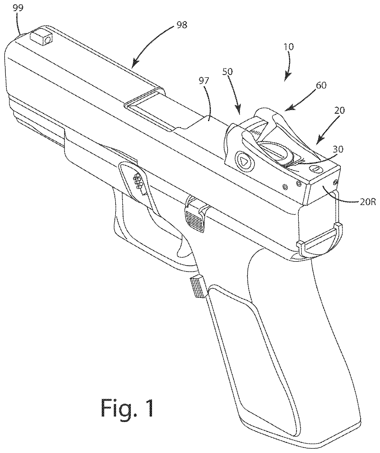
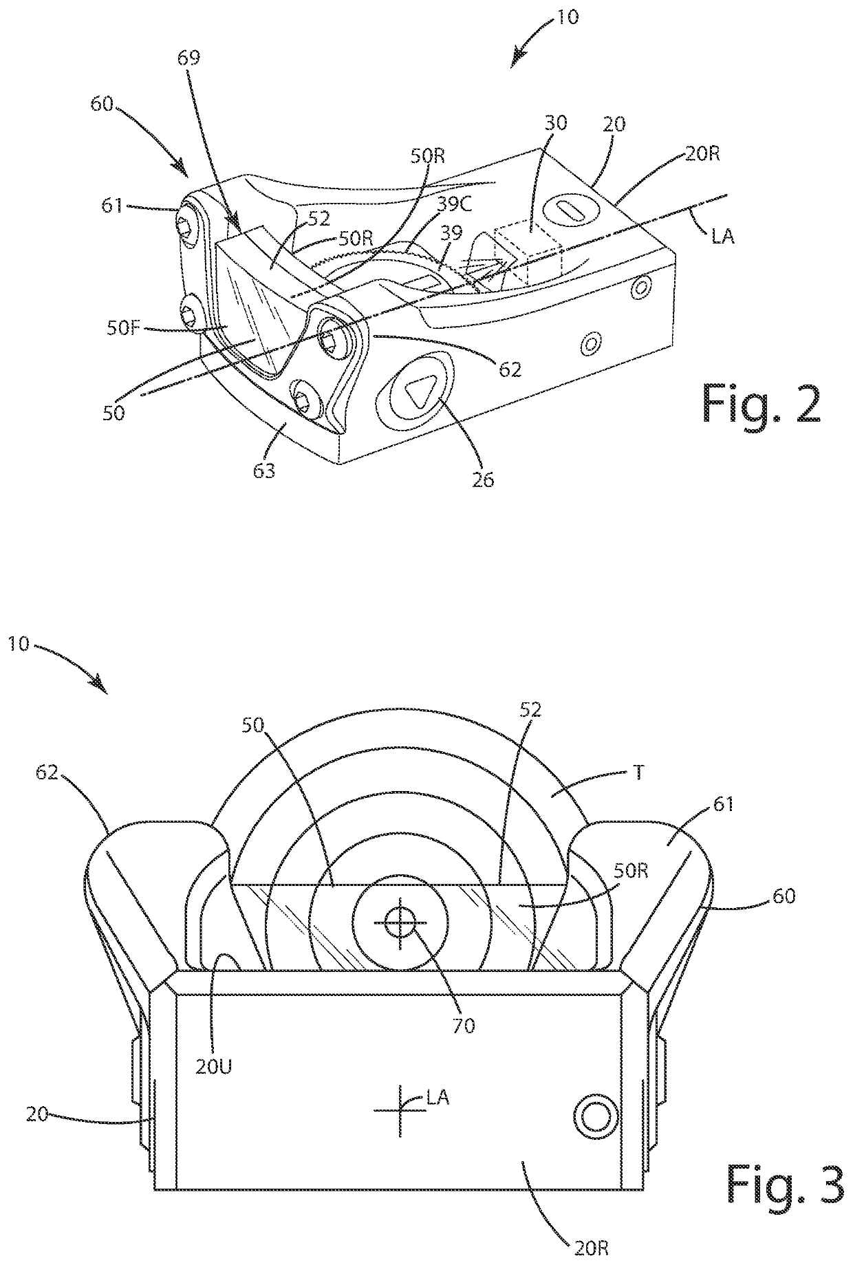
[0052]A current embodiment of the aiming system, also referred to as a sight herein is illustrated in FIGS. 1-10 and generally designated 10. To begin, the sight 10 is shown mounted on a semi-automatic pistol. The sight 10 can, however, be mounted on other types of projectile shooting devices. For example, it can be mounted to other types of firearms, including but not limited to a rifle (for example, a long rifle, a carbine, an assault rifle, a bolt pump rifle or a battle rifle); a shotgun (of any gauge) and / or a machine gun (for example, a machine pistol, a light machine gun, a mini gun, a medium machine gun or a heavy machine gun). The firearm can include any type of action, for example, bolt action, lever action, pump action and / or break action. The firearm can be single shot, automatic and / or semiautomatic. Further optionally, the firearm can be in the form of a vehicle-mounted weapon, mounted directly to the vehicle, a watercraft or other mode of transportation of course. As u...


PUM


Abstract

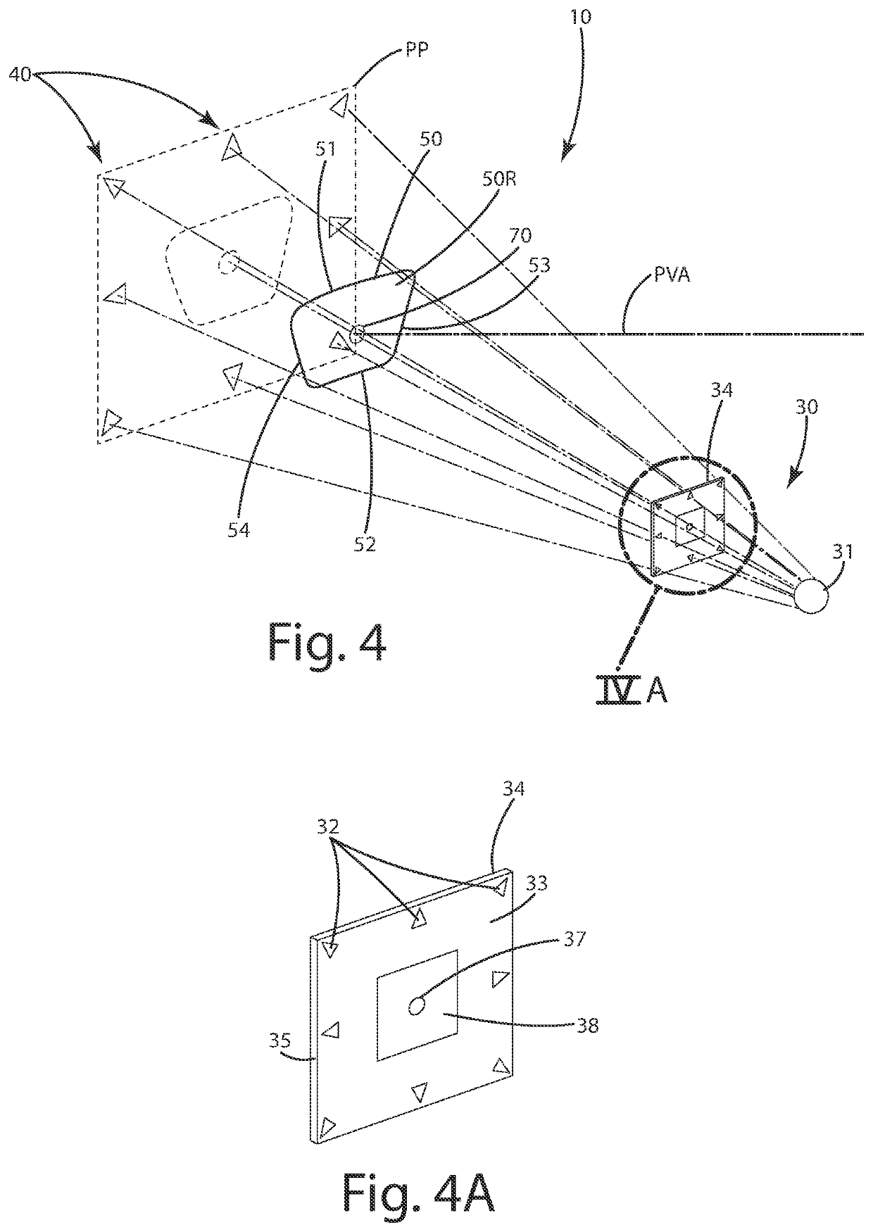
An aiming device is provided including an illumination device and an optical element wherein the illumination device projects a primary dot and at least one secondary alignment dot distal from the primary dot to aid a user in obtaining a view of the primary dot when the aiming device is in an aligned mode, the primary dot is visible within a field of view of the user, but the secondary alignment dot is not visible. When the aiming device is in a misaligned mode, the secondary alignment dot is visible to the user, but the primary dot is not. The secondary alignment dot provides instruction to the user to realign the aiming device relative to the field of view of the user so that the aiming device transitions to the aligned mode. A related method of operation is provided.

Description

BACKGROUND OF THE INVENTION[0001]The present invention relates to aiming devices, and more particularly to reflex aiming devices having a macro alignment reticle or other reticle alignment aids.[0002]The popularity and use of firearms for hunting, target shooting, and other dynamic shooting sports, has increased over the past several decades. The fast-paced, competitive nature of shooting and the desire by hunters to have well-placed, ethical shots, have led to the development and commercialization of a variety of aiming devices. These devices include fiber optic sights, illuminated scope reticles and reflex sights, to name a few.[0003]Reflex sights typically are used with firearms in a variety of shooting sports and hunting activities where quick target acquisition is favorable. Such sights superimpose a bright illuminated dot against a center of a lens or window in a protective frame. The firearm is aimed by placing the superimposed dot on a target as viewed through the window. Du...

Claims


Application Information

Patent Timeline
Patent Type & Authority Applications(United States)
IPC IPC(8): F41G1/54F41G1/34F41G1/30
CPCF41G1/545F41G1/30F41G1/345
Inventor GRACE, NATHANIEL E.
Owner GRACE ENG
Learn More