
Methods for reducing image artifacts during partial updates of electrophoretic displays

Active Publication Date: 2022-05-05
E INK CORPORATION
View PDF0 Cites 0 Cited by
  • Summary
  • Abstract
  • Description
  • Claims
  • Application Information

AI Technical Summary

Benefits of technology

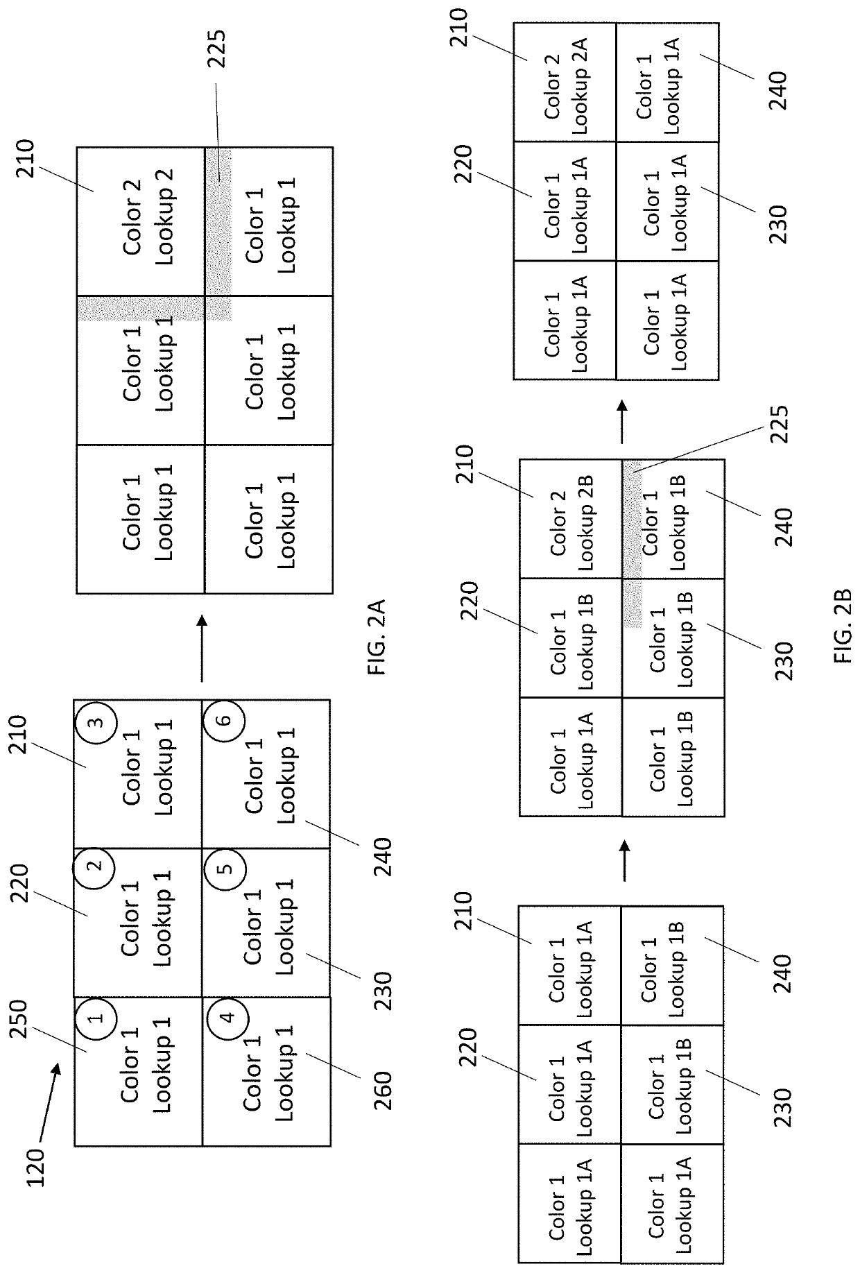
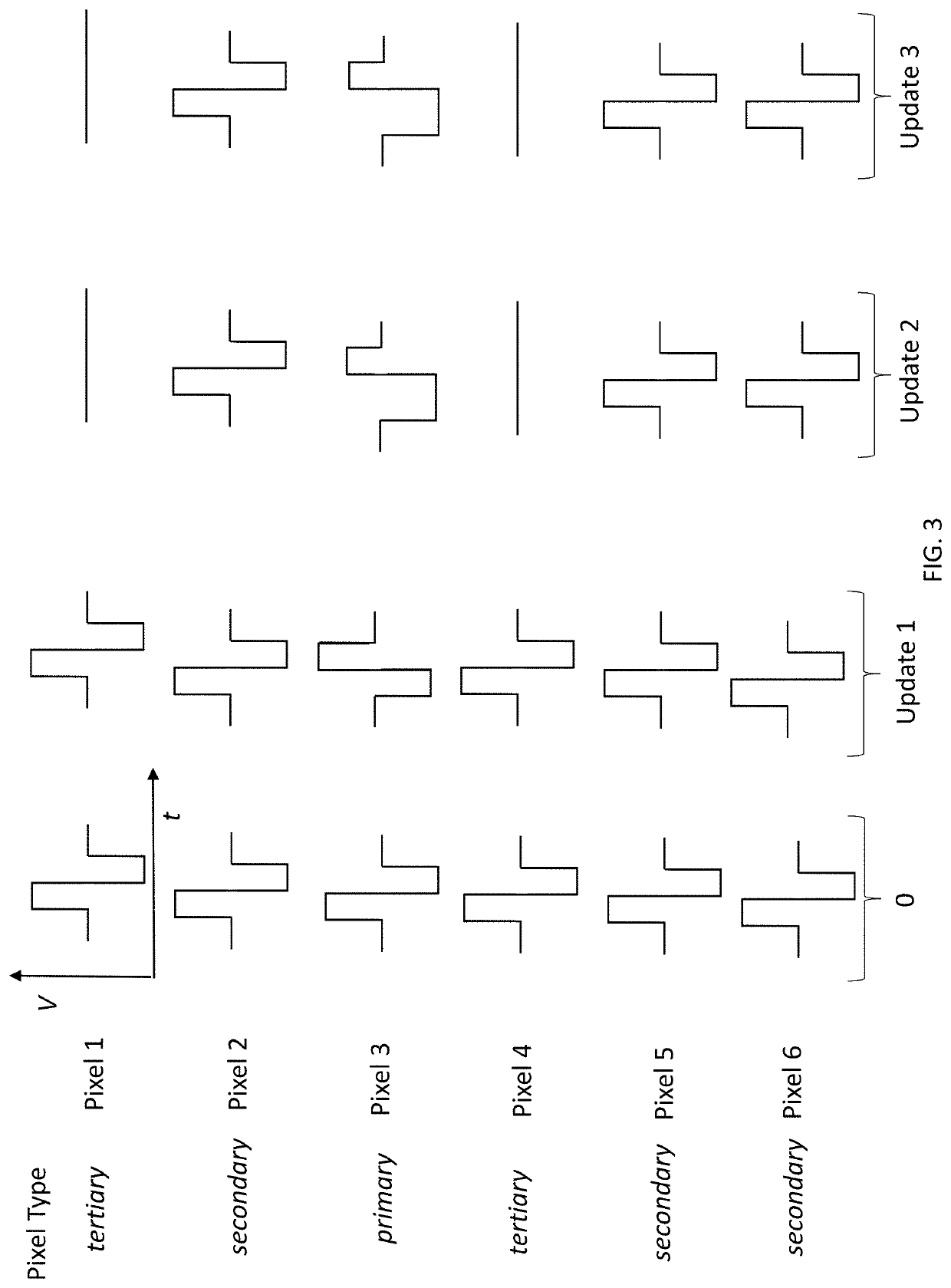
The invention provides a method to reduce or eliminate edge artifacts in a camera system. This method uses two sets of control instructions for each optical state to update pixels along a straight edge. By updating neighboring pixels at the same time, the method prevents artifacts from occurring. The method also reduces the visibility of edge artifacts, making them less noticeable.

Problems solved by technology

Driving neighboring pixels in this manner greatly reduces the visibility of edge artifacts, such as blooming, since any edge artifacts occurring along the edge defined by the extra pixels are much less conspicuous than would be without these methods.

Method used


Image

  • Methods for reducing image artifacts during partial updates of electrophoretic displays
  • Methods for reducing image artifacts during partial updates of electrophoretic displays
  • Methods for reducing image artifacts during partial updates of electrophoretic displays

Examples


Embodiment Construction

[0052]The method of the present invention seeks to reduce or eliminate edge artifacts which occur along a straight edge between driven and undriven pixels. The human eye is especially sensitive to linear edge artifacts, especially ones which extend along the rows or columns of a display. In this method, a number of pixels lying adjacent an edge between the driven and undriven areas are in fact driven, such that any edge effects caused by the transition are hidden or otherwise minimized.

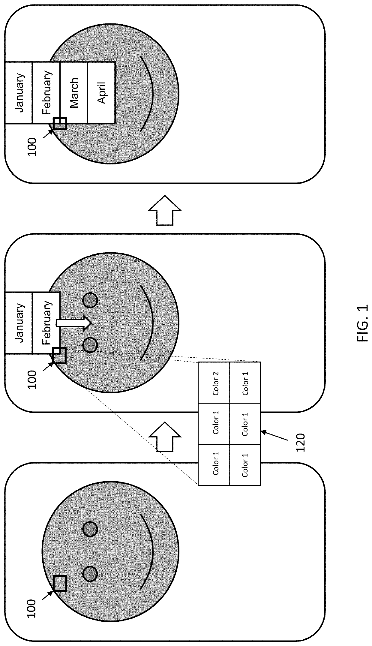
[0053]As discussed above, partial updates are typically used when only a portion of the image requires updating, such as pull-down menus, scrolling text, or simplified animation. An example is shown in FIG. 1, wherein a pull-down menu is advanced over an existing image. A subset of pixels 100 in a small area of the display will undergo disparate color transitions as the pull-down menu is advanced. For example, some pixels will change from dark to light and some pixels will not change their optical sta...


PUM


Abstract

A method for driving electro-optic displays so as to reduce visible artifacts are described. Such methods include driving extra pixels where the boundary between a driven and undriven area would otherwise lead to artifact by providing paired sets of driving instructions, allowing the undriven area to be driven while maintain the desired (undriven) optical state.

Description

REFERENCE TO RELATED APPLICATIONS[0001]This application claims priority to U.S. Provisional Patent Application No. 63 / 108,852, filed Nov. 2, 2021. All patents and publications disclosed herein are incorporated by reference in their entireties.BACKGROUND OF INVENTION[0002]The present invention relates to methods for driving electro-optic displays, especially bistable electro-optic displays, and to apparatus for use in such methods. More specifically, this invention relates to driving methods which may allow for reduced “ghosting”, “blooming” or other edge effects during partial updates of the display. This invention is especially, but not exclusively, intended for use with particle-based electrophoretic displays in which one or more types of electrically charged particles are present in a fluid and are moved through the fluid under the influence of an electric field to change the appearance of the display. The methods are broadly applicable to a bistable electro-optic medium where it...

Claims


Application Information

Patent Timeline
IPC IPC(8): G09G3/34
CPCG09G3/344G09G5/06G09G2230/00G09G2380/14G09G2310/04G09G2320/0209G09G2310/06G09G2320/0257
Inventor CROUNSE, KENNETH R.BEN-DOV, YUVALTELFER, STEPHEN J.KUMAR, JAYA
Owner E INK CORPORATION
Learn More