Article Transport Facility

a technology for transporting facilities and objects, applied in the direction of conveyor parts, transportation and packaging, conveyors, etc., can solve the problems of complicated control configuration, shorten the positioning time of holding units, and achieve high lifting operation gain, shorten the positioning time of holding units, and reduce the effect of control configuration

Pending Publication Date: 2022-03-17
DAIFUKU CO LTD
View PDF0 Cites 0 Cited by
  • Summary
  • Abstract
  • Description
  • Claims
  • Application Information

AI Technical Summary

Benefits of technology

[0007]In order to shorten the positioning time of a holding unit and the like, it is generally sought to set the gain of feedback control during the lifting operation of the holding unit by the lifting unit (lifting operation gain) comparatively high. According to this configuration, the gain of feedback control during the travel operation of the travel unit (travel operation gain) can be set low, while setting a high lifting operation gain. By setting a low travel operation gain in this way, in the case where the holding unit is displaced from the target position during the travel operation, the amount of corrective force for returning the position of the holding unit in the lifting direction to the target position can be kept at a moderate level, and vibration that is transmitted to the article held by the holding unit can be kept small. In this way, according to this configuration, vibration in the vertical direction that is transmitted to the article during the travel operation of the travel unit can be reduced, with a comparatively simple control configuration that reduces the travel operation gain to lower than the lifting operation gain.

Problems solved by technology

Thus, the control configuration tends to become complicated, compared with the case where such a vibration suppression torque generation system is unnecessary.

Method used


Image

  • Article Transport Facility
  • Article Transport Facility
  • Article Transport Facility

Examples


Embodiment Construction

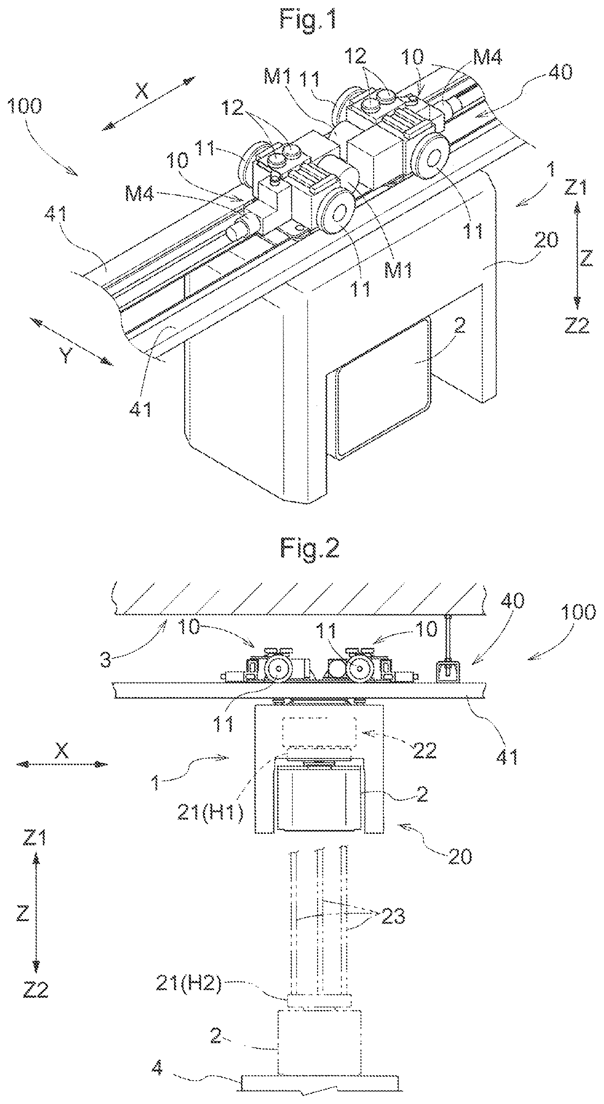
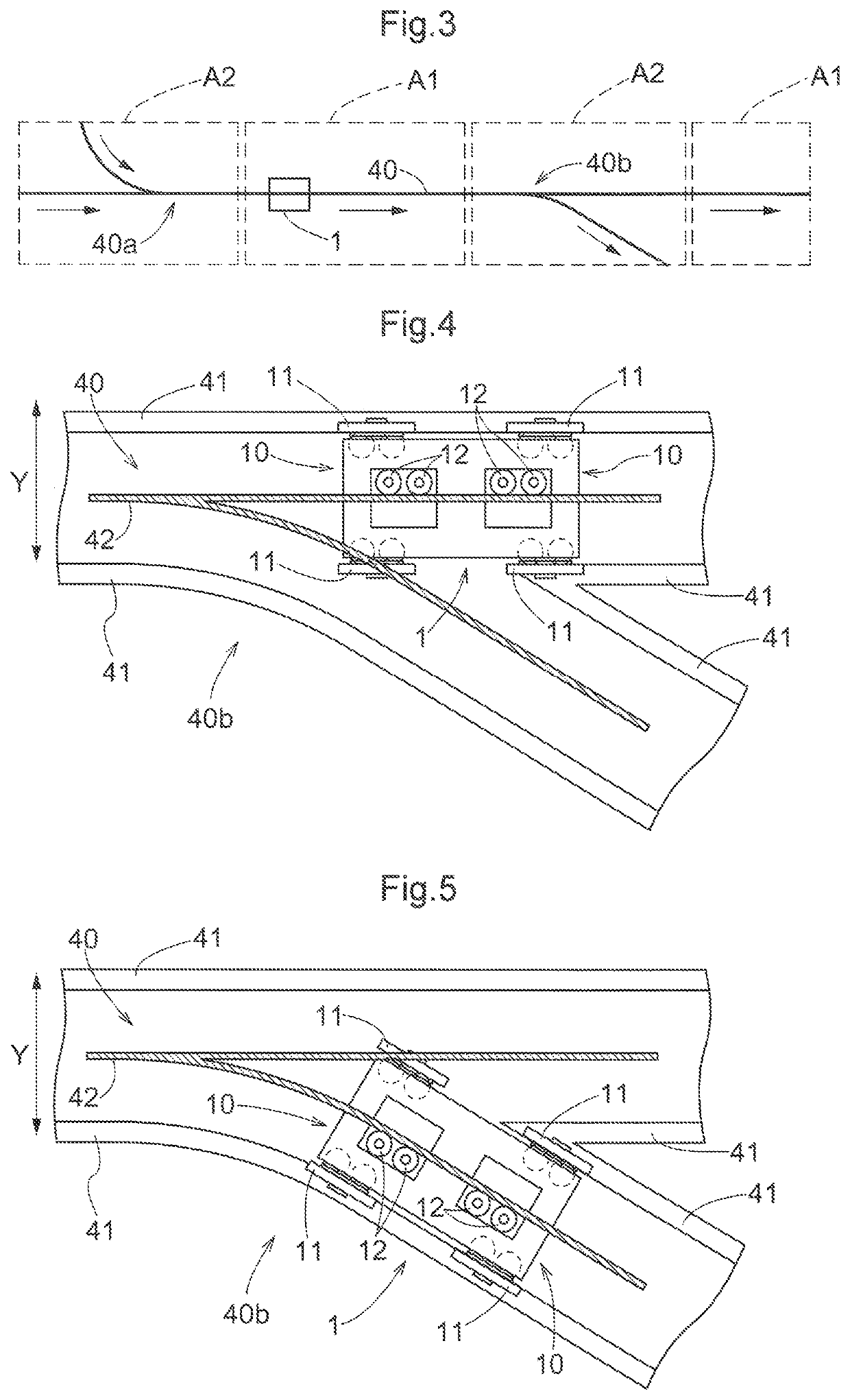
[0017]An embodiment of an article transport facility will be described with reference to the drawings. As shown in FIG. 1, an article transport facility 100 is provided with a transport vehicle 1 that travels along a travel path 40 and transports an article 2. Here, the longitudinal direction of the travel path 40 (direction in which the travel path 40 extends) is a path longitudinal direction X, and the width direction of the travel path 40 is a path width direction Y. The path width direction Y is a direction orthogonal to both the path longitudinal direction X and the vertical direction Z.

[0018]In the present embodiment, the article transport facility 100 is provided with a travel rail 41 disposed along the travel path 40 (here, a pair of travel rails 41 disposed with an interval therebetween in the path width direction Y), and the transport vehicle 1 travels along the travel rail 41. As shown in FIG. 2, in the present embodiment, the transport vehicle 1 is a ceiling transport ve...


PUM


Abstract

A control unit causes a lifting unit to perform a lifting operation for raising/lowering a holding unit by executing feedback control for controlling the lifting unit to move a position of the holding unit in a lifting direction closer to a target position while changing the target position, and the control unit executes feedback control with the target position fixed while causing the travel unit to perform a travel operation for traveling along a travel path in a state where the holding unit is holding an article. The control unit reduces a travel operation gain which is a gain of the feedback control during the travel operation to lower than a lifting operation gain which is a gain of the feedback control during the lifting operation.

Description

CROSS-REFERENCE TO RELATED APPLICATION[0001]This application claims priority to Japanese Patent Application No. 2020-153136 filed Sep. 11, 2020, the disclosure of which is hereby incorporated by reference in its entirety.BACKGROUND OF THE INVENTION1. Field of the Invention[0002]The present invention relates to an article transport facility provided with a transport vehicle that travels along a travel path and transport an article, and a control unit that controls operations of the transport vehicle.2. Description of the Related Art[0003]An example of an article transport facility such as the above is disclosed in JP 2017-124885A (Patent Document 1). Hereinafter, reference numerals shown in parentheses in the description of this section are from Patent Document 1. The article transport facility of Patent Document 1 is provided with an article transport device (2) that travels along a travel path and transports an article (3), and a control device (80) that controls operations of the ...

Claims


Application Information

Patent Timeline
Patent Type & Authority Applications(United States)
IPC IPC(8): B65G43/02B66C19/00B66C13/30B61B13/00H01L21/677
CPCB65G43/02B66C19/00B66C13/30B61B13/00B65G2201/0297H01L21/67763B65G2203/0283B65G2203/0291H01L21/67733B65G35/00B66C13/063B66C9/14B66C9/02B66C9/04H01L21/67736H01L21/67715H01L21/67706H01L21/6773H01L21/67259B65G1/0457
Inventor OTSUKA, HIROSHI
Owner DAIFUKU CO LTD
Why Eureka
Try Eureka