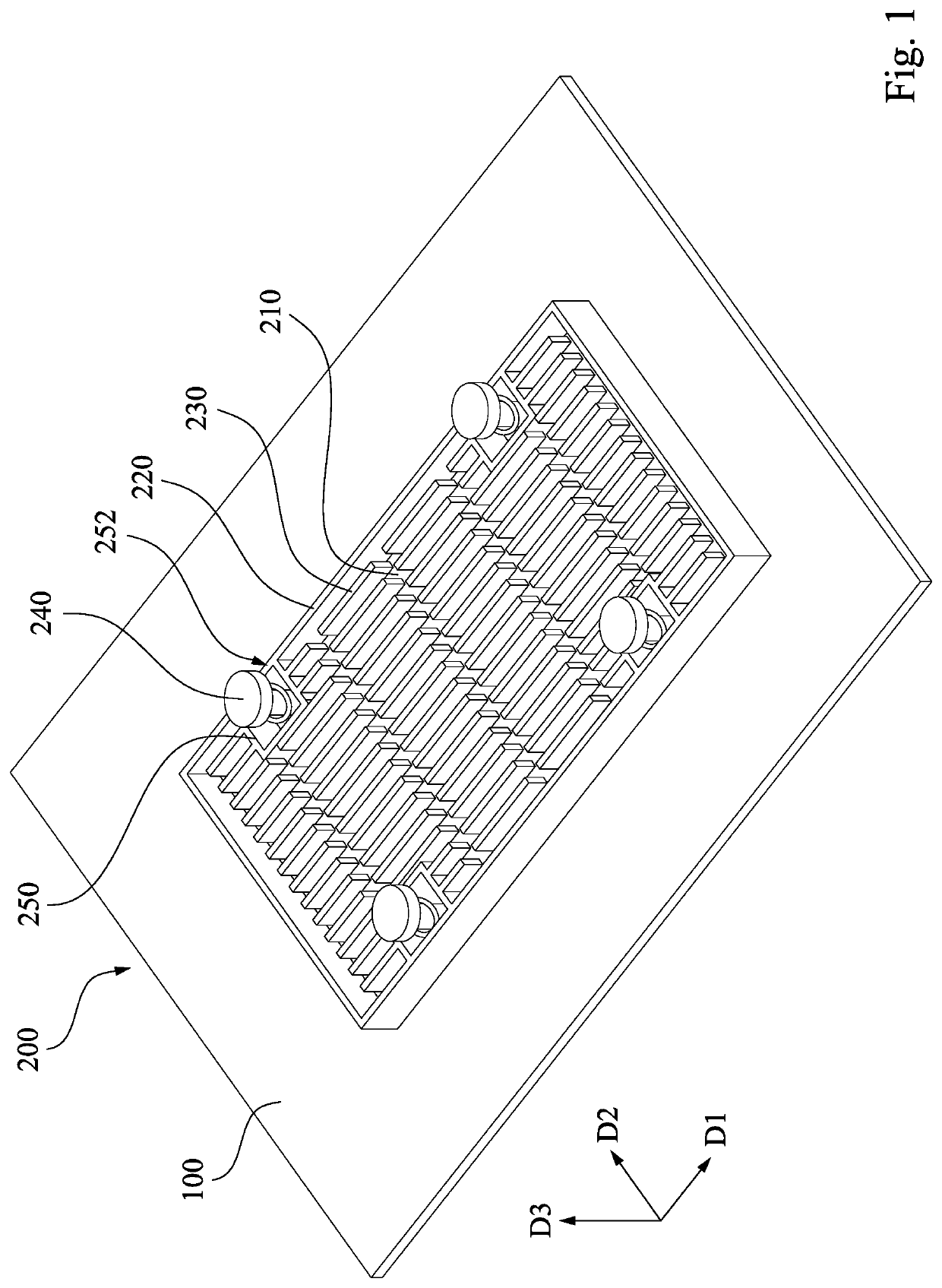
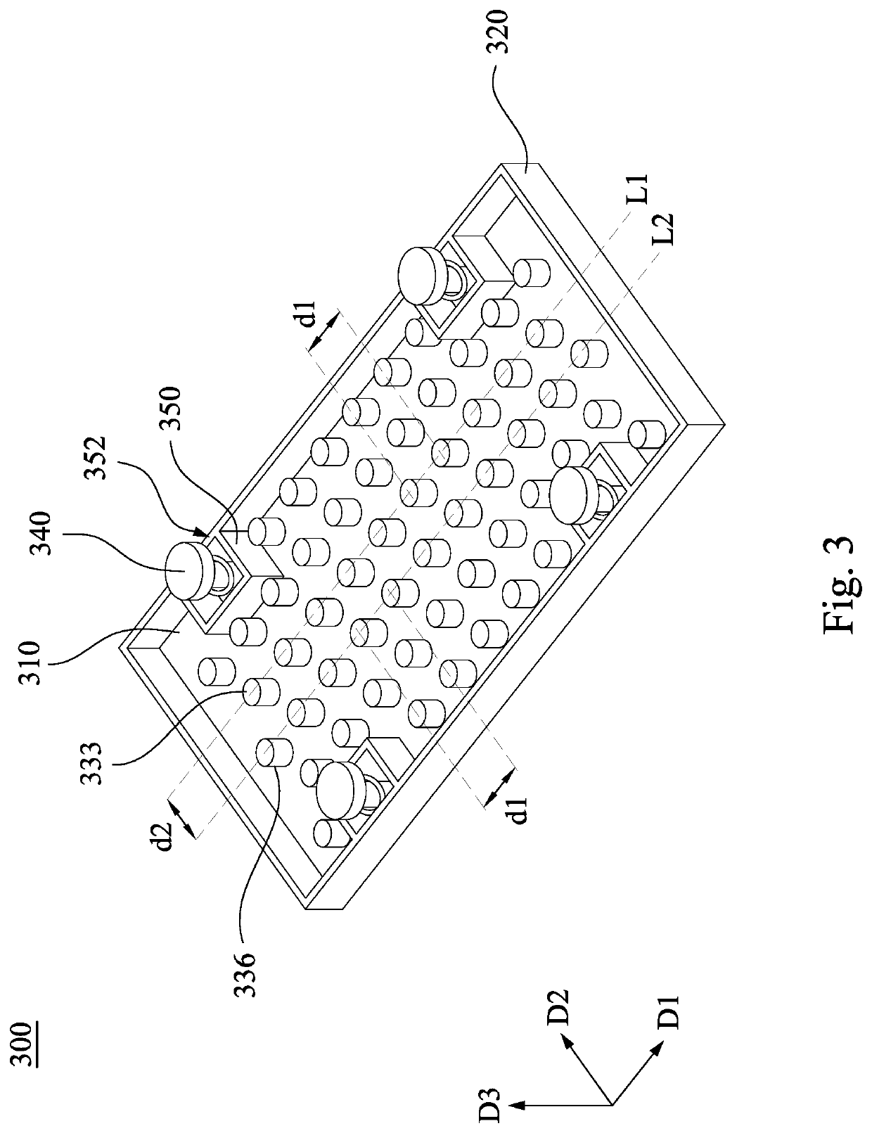
Heat sink and thermal dissipation structure

Pending Publication Date: 2022-03-10
INVENTEC PUDONG TECH CORPOARTION +1
View PDF5 Cites 0 Cited by
  • Summary
  • Abstract
  • Description
  • Claims
  • Application Information

AI Technical Summary

Benefits of technology

The present invention provides a heat sink with a liquid barrier structure and heat conducting fins. These fins help to decrease the resistance and improve the flow of the coolant droplets that come in contact with them. This heat sink can be used in thermal dissipation structures.

Problems solved by technology

This makes the heat exchange effect of the liquid droplets for cooling limited, resulting in poor overall temperature uniformity of the heat sink and reducing the heat dissipation effect.

Method used


Image

  • Heat sink and thermal dissipation structure
  • Heat sink and thermal dissipation structure
  • Heat sink and thermal dissipation structure

Examples


Embodiment Construction

[0026]The following embodiments are disclosed with accompanying diagrams for detailed description. For illustration clarity, many details of practice are explained in the following descriptions. However, it should be understood that these details of practice do not intend to limit the present invention. That is, these details of practice are not necessary in parts of embodiments of the present invention. Furthermore, for simplifying the drawings, some of the conventional structures and elements are shown with schematic illustrations. Also, the same labels may be regarded as the corresponding components in the different drawings unless otherwise indicated. The drawings are drawn to clearly illustrate the connection between the various components in the embodiments, and are not intended to depict the actual sizes of the components.

[0027]In addition, terms used in the specification and the claims generally have the usual meaning as each terms are used in the field, in the context of th...


PUM


Abstract

A heat sink includes a bottom plate, a liquid barrier structure and a plurality of heat conducting fins. The liquid barrier structure is located on the periphery of the bottom plate. The heat conducting fins are arranged on the bottom plate. The heat conducting fins are located in the liquid barrier structure.

Description

RELATED APPLICATIONS[0001]This application claims priority to China Application Serial Number 202010931836.9, filed Sep. 8, 2020, which are herein incorporated by reference.BACKGROUNDField of Invention[0002]The present invention relates to a heat sink and a thermal dissipation structure.Description of Related Art[0003]For conventional heat sink with directional fin design, liquid droplets used for cooling can only be dropped on the grooves between fins of heat sinks such that the liquid droplets can only flow forward or backward in a single direction in the grooves. This makes the heat exchange effect of the liquid droplets for cooling limited, resulting in poor overall temperature uniformity of the heat sink and reducing the heat dissipation effect.[0004]Therefore, how to provide a solution for the above mentioned problem is one of the subjects to be solved for the industry.SUMMARY[0005]To achieve the above object, an aspect of the present invention is related to a heat sink used t...

Claims


Application Information

Patent Timeline
IPC IPC(8): F28F3/06
CPCF28F3/06H05K7/20418H05K7/20254F28D2021/0028F28C3/005F28F3/022F28F3/048H05K7/20309
Inventor TUNG, KAI-YANGCHEN, HUNG-JU
Owner INVENTEC PUDONG TECH CORPOARTION
Why Eureka
Try Eureka