Maximum-power tracker

A maximum power tracking and converter technology, which is applied in the direction of output power conversion devices, instruments, DC power input conversion to DC power output, etc., can solve the problem of increased cost of maximum power tracker, low efficiency of maximum power tracker, and high peak value Problems such as current and power loss, to achieve the effect of maximizing efficiency, improving efficiency, and reducing current resistance

Inactive Publication Date: 2014-01-01
JIAXING KAIXI ELECTRONICS
View PDF4 Cites 1 Cited by
  • Summary
  • Abstract
  • Description
  • Claims
  • Application Information

AI Technical Summary

Problems solved by technology

Conventional buck maximum power trackers such as figure 1 As shown, it is realized by using the maximum power point tracking (MPPT circuit) (not shown in the figure) together with the BUCK DC converter. It is connected to the positive and negative poles of the output terminal of the wind turbine or solar cell module, and the positive pole c and negative pole d of the output terminal are also directly connected to the positive and negative poles of the input terminal of the battery or low-voltage load. This topology is easy to cause high peak current and power loss, especially when there is a large difference between the input and output voltages, the requirements for current resistance of the electronic devices in the maximum power tracker will be increased, so the cost of the maximum power tracker will be greatly increased, and the service life will naturally be affected, and Maximum power tracker is also less efficient due to higher power dissipation

Method used


Image

  • Maximum-power tracker
  • Maximum-power tracker
  • Maximum-power tracker

Examples


Embodiment Construction

[0016] The present invention will be further described below in conjunction with the accompanying drawings:

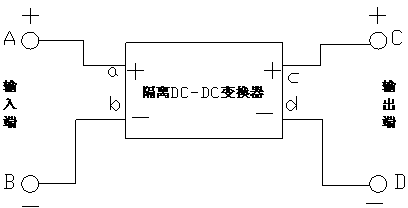
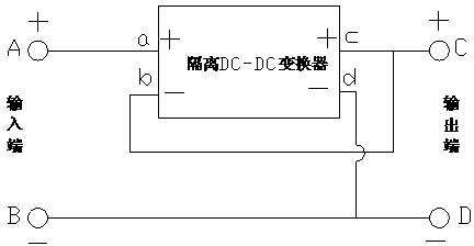
[0017] like figure 2 As shown in the figure, a maximum power tracker of the present invention includes an input positive terminal A, an input negative terminal B, an output positive terminal C, an output negative terminal D, and also includes an input terminal positive terminal a and an input terminal negative terminal b. An isolated DC-DC converter with the positive electrode c of the output end and the negative electrode d of the output end, wherein the positive electrode a of the input end of the isolated DC-DC converter is electrically connected to the positive terminal A of the input end, and the positive electrode c of the output end of the isolated DC-DC converter is electrically connected It is electrically connected to the positive terminal C of the output terminal, the negative terminal d of the output terminal of the isolated DC-DC converter is electrically...


PUM


Abstract

The invention discloses a maximum-power tracker which comprises an input end positive electrode connector, an input end negative electrode connector, an output end positive electrode connector, and an output end negative connector. The maximum-power tracker further comprises an insulating DC-DC converter with an input end positive electrode, an input end negative electrode, an output end negative electrode, and an output end negative electrode. The input end positive electrode of the insulating DC-DC converter is electrically connected with the input end positive electrode connector. The output end positive electrode of the insulating DC-DC converter is electrically connected with the output end positive electrode connector. The output end negative electrode of the insulating DC-DC converter is electrically connected with the output end negative electrode connector. The input end negative electrode of the insulating DC-DC converter is electrically connected with the output end positive electrode connector C. The output end negative electrode connector is electrically connected with the input end negative electrode connector. Due to the fact that the input end negative electrode of the insulating DC-DC converter is electrically connected with the output end positive electrode and the output end positive electrode connector, a part of voltage is overlapped outside the converter, the efficiency of the whole system is made to be maximized, and voltage withstanding requirements for power and electronic elements of the converter are reduced. Consequently, cost is reduced, and the service life is prolonged.

Description

Technical field: [0001] The invention relates to a power electronic device of a new energy power generation system, in particular to a maximum power tracker. [0002] Background technique: [0003] With the continuous development of wind power generation and solar power generation technology, in order to charge the battery or to supply power for low-voltage loads, it is often necessary to convert these higher voltage electricity into low-voltage electricity. power, so maximum power trackers have become popular, and maximum power trackers use power electronics with appropriate software to keep these wind turbines or solar modules outputting maximum power at all times. Traditional buck MPPTs such as figure 1 As shown in the figure, it is realized by using the maximum power point tracking or MPPT circuit (not shown in the figure) to cooperate with the BUCK DC converter. It is connected with the positive and negative poles of the output terminal of the wind turbine or solar c...

Claims


Application Information

Patent Timeline
IPC IPC(8): H02M3/00
Inventor 曹艳辉寇青
Owner JIAXING KAIXI ELECTRONICS
Why Eureka
Try Eureka