
landslide Deep Displacement Remote Visual Monitoring System

a remote visual monitoring and deep displacement technology, applied in transmission systems, earthquake measurement, instruments, etc., can solve the problems of inability to centralize management, consume too much manpower, and the monitoring system cannot perform remote visual real-time monitoring, so as to reduce the number of landslide accidents, reduce the waste of manpower and material resources, and effectively monitor the displacement situation of each poin

Inactive Publication Date: 2022-03-03
GAN JIANJUN +2
View PDF0 Cites 2 Cited by
  • Summary
  • Abstract
  • Description
  • Claims
  • Application Information

AI Technical Summary

Benefits of technology

The invention allows for real-time monitoring of landslide data and can be customized for computer manual supervision. It uses double insurance to reduce landslide accidents caused by human monitoring errors. Remote management can gather data from multiple monitoring points in one place for centralized management, avoiding waste of resources. The use of anchor points eliminates the need for prefabricated wells, resulting in higher safety factors. The data acquisition unit is arranged on the displacement sensor through wires to collect data and send it through network transmission module, ensuring transmission efficiency and speed. The data receiving module is connected to the computer through a data cable to input the data image directly, making the reading more efficient.

Problems solved by technology

However, the prior monitoring system cannot perform remote visual real-time monitoring, and requires local monitoring points to be built for monitoring, which cannot be centralized management and consumes too much manpower.

Method used


Image

  • landslide Deep Displacement Remote Visual Monitoring System
  • landslide Deep Displacement Remote Visual Monitoring System
  • landslide Deep Displacement Remote Visual Monitoring System

Examples


Embodiment Construction

[0016]The invention is further described in detail with reference to the accompanying drawings.

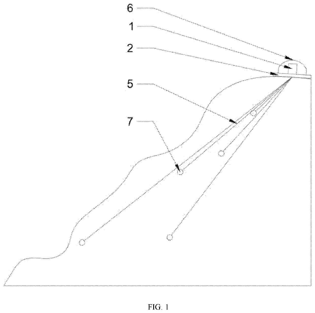
[0017]In specific embodiment, a landslide deep displacement remote visual monitoring system, comprising monitoring system and transmitting system, wherein the monitoring system comprises displacement sensor 1, the displacement sensor 1 is arranged on chassis 2, anchor eyes 3 are provided on the chassis 2, wire embedding hole 4 is arranged at centroid of the chassis 2, multiple bracing wires 5 are provided in the wire embedding hole 4, a dust protection cover 6 is provided on outer side of the displacement sensor 1, anchor points 7 are provided on the end of the bracing wires 5 far away from the displacement sensor 1, and the length of the multiple bracing wires 5 is different, the distribution angle of the anchor points 7 is not limited, and the embedded depth of the anchor points 7 is different, a solar panel is arranged on surface of the chassis 2 to supply power to the displacement sens...


PUM


Abstract

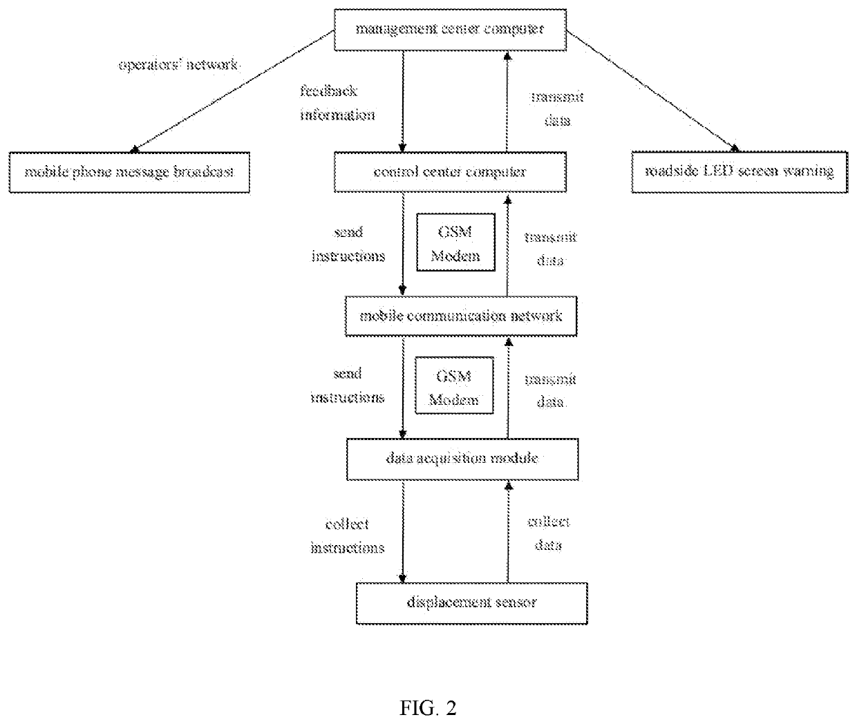
The invention discloses a landslide deep displacement remote visual monitoring system, comprising monitoring system and transmitting system, the monitoring system comprises displacement sensor, the displacement sensor is arranged on chassis, anchor eyes are provided on the chassis, wire embedding hole is arranged at centroid of the chassis, multiple bracing wires are provided in the wire embedding hole, the transmitting system comprises a data acquisition unit, the data acquisition unit is arranged on the displacement sensor for collecting data thereof, the data acquisition unit is connected to a network transmission module, the network transmission module is connected to a data receiving module through the network, the data receiving module is also provided with network transmission module, the data receiving module is connected to computer, the computer displays the data through display screen.

Description

BACKGROUND OF THE INVENTION1. Field of the Invention[0001]The invention relates to landslide monitoring device, in particular to a landslide deep displacement remote visual monitoring system.2. Description of the Related Art[0002]Landslide refers to a natural phenomenon that the soil or rock mass on the slope, affected by river degradation, groundwater activity, rainwater soaking, earthquake and artificial slope cutting, slides down the slope integrally or dispersedly under the action of gravity and along a certain weak surface or weak zone. The moving soil or rock mass is called displacement body or slipping body, the unmoved underlying soil or rock mass is called slide bed.[0003]Landslide monitoring belongs to discipline of natural disasters and prevention for observing and analyzing various landslide precursor phenomena and recording various tasks of landslide formation activities. Various crack development processes in different parts of the slope, rock and soil mass relaxation ...

Claims


Application Information

Patent Timeline
Patent Type & Authority Applications(United States)
IPC IPC(8): G01V1/00G01V1/20G01V1/34G08B21/10H04W4/90
CPCG01V1/008G01V1/003H04W4/90G01V1/34G08B21/10G01V1/202G01B7/02G08C17/02H04W4/38G01V1/201G08B27/00G01V1/01
Inventor GAN, JIANJUNLI, JIANHUALI, XIAOMING
Owner GAN JIANJUN
Learn More