
Monitoring device, monitoring system, monitoring method, and program

a monitoring device and monitoring system technology, applied in the direction of measurement devices, measurement devices, instruments, etc., can solve the problems of pipe inner surface thickness reduction over time, harsh environment, etc., and achieve the effect of quick and accurate detection of abnormalities

Pending Publication Date: 2022-02-24
MITSUBISHI HEAVY IND LTD
View PDF0 Cites 0 Cited by
  • Summary
  • Abstract
  • Description
  • Claims
  • Application Information

AI Technical Summary

Benefits of technology

The invention is a monitoring system that uses data on the thickness of a pipe's wall to quickly and accurately detect any abnormalities in the pipe. This helps to prevent damage or leaks which could cause significant damage or discomfort to people and environments.

Problems solved by technology

High-temperature and high-pressure water and steam flow through pipes installed in power plants, chemical plants, and the like, and the pipes are exposed to harsh environments.
Therefore, thickness reduction over time occurs on an inner surface of the pipe due to corrosion, abrasion, or a combination thereof.

Method used


Image

  • Monitoring device, monitoring system, monitoring method, and program
  • Monitoring device, monitoring system, monitoring method, and program
  • Monitoring device, monitoring system, monitoring method, and program

Examples


first embodiment

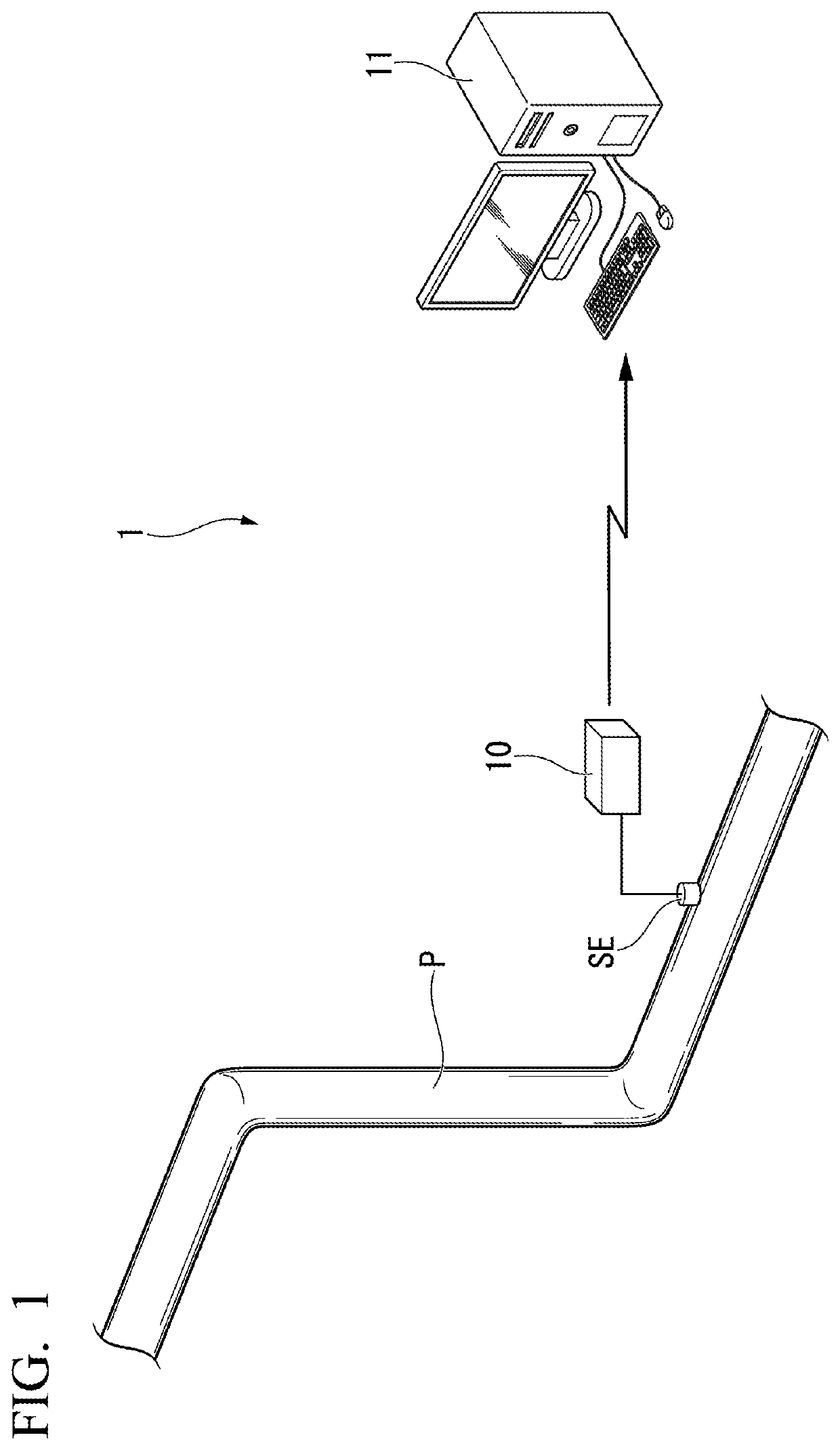
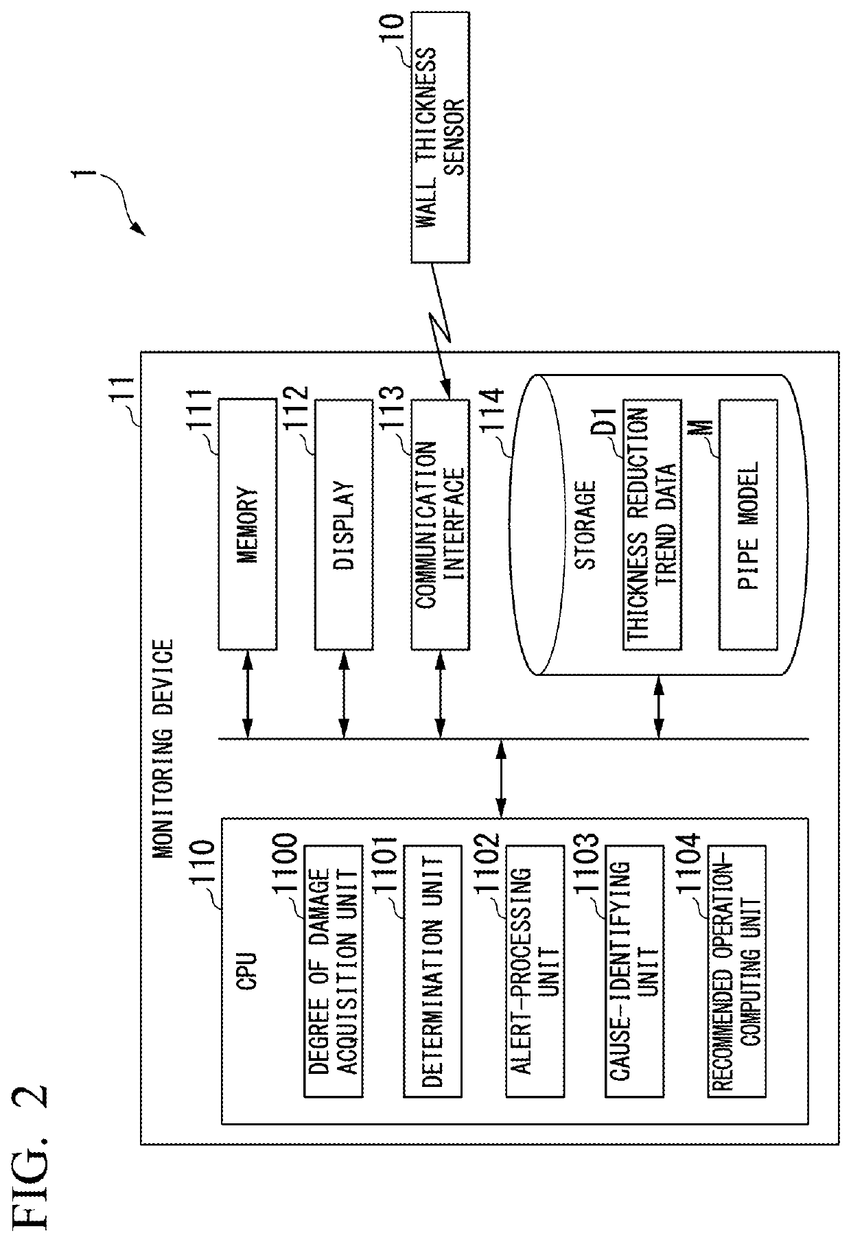
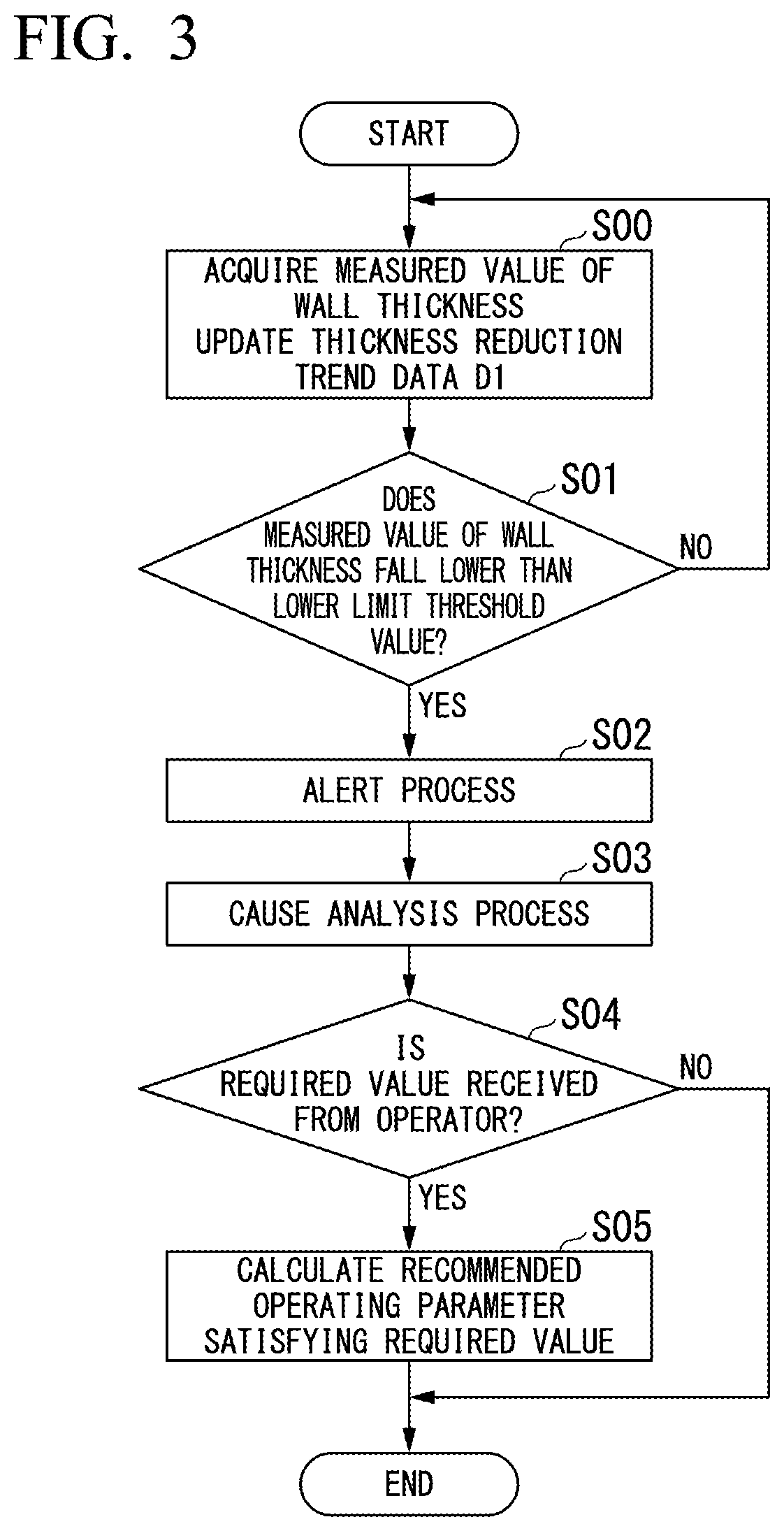
[0025]Hereinafter, a monitoring device according to the first embodiment and a monitoring system including the same will be described with reference to FIG. 1 to FIG. 7.

[0026](Overall Configuration of Monitoring System)

[0027]FIG. 1 is a diagram showing an overall configuration of a monitoring system according to the first embodiment.

[0028]A monitoring system 1 according to the present embodiment may be applied to, for example, a carbon steel pipe (hereinafter, also referred to as a “pipe P”) of a secondary cooling system in a nuclear power plant. According to such an aspect, since high-temperature water and steam flow through the pipe P, an inner surface of the pipe gradually wears and thickness reduction occurs overtime.

[0029]In other embodiments, the monitoring system 1 can also be applied to plant facilities and pipes other than a nuclear power plant.

[0030]As shown in FIG. 1, the monitoring system 1 includes a wall thickness sensor 10 and a monitoring device 11.

[0031]The wall thi...


PUM

PropertyMeasurementUnit
thresholdaaaaaaaaaa
thicknessaaaaaaaaaa
temperatureaaaaaaaaaa

Abstract

A monitoring device is provided that is capable of quickly and accurately detecting the occurrence of an abnormality in a pipe on the basis of the trend of the wall thickness of the pipe. The monitoring device includes a degree of damage acquisition unit configured to acquire a degree of damage to a pipe, and a determination unit configured to determine whether the degree of damage has fallen lower than a lower limit threshold value determined on the basis of a reference operating parameter related to fluid flowing through the pipe.

Description

TECHNICAL FIELD[0001]The present invention relates to a monitoring device, a monitoring system, a monitoring method, and a program.[0002]Priority is claimed on Japanese Patent Application No. 2018-171906, filed Sep. 13, 2018, the content of which is incorporated herein by reference.BACKGROUND ART[0003]High-temperature and high-pressure water and steam flow through pipes installed in power plants, chemical plants, and the like, and the pipes are exposed to harsh environments. Therefore, thickness reduction over time occurs on an inner surface of the pipe due to corrosion, abrasion, or a combination thereof. In order to prevent the pipe from being damaged due to such thickness reduction, it is required to manage the wall thickness of the pipe (for example, see Patent Literature 1).CITATION LISTPatent Literature[Patent Literature 1][0004]Japanese Unexamined Patent Application, First Publication No. 2001-280600SUMMARY OF INVENTIONTechnical Problem[0005]There is a need to precisely ascer...

Claims


Application Information

Patent Timeline
Patent Type & Authority Applications(United States)
IPC IPC(8): G01B17/02G01N29/07
CPCG01B17/02G01N2291/02854G01N29/07G01M99/00G05B23/02
Inventor KOBAYASHI, TAKAAKIITAHASHI, YUMAKODAIRA, TAKESHI
Owner MITSUBISHI HEAVY IND LTD
Learn More