
Apparatus, methods, and computer programs for obtaining an image of a sample

a sample and image technology, applied in the field of apparatus, methods, computer programs for obtaining an image of a sample, can solve the problem of increasing the rate of image resolution degradation

Pending Publication Date: 2022-02-24
NOKIA TECHNOLOGLES OY
View PDF1 Cites 0 Cited by
  • Summary
  • Abstract
  • Description
  • Claims
  • Application Information

AI Technical Summary

Benefits of technology

The patent describes an apparatus and method for using optical frequency imaging to obtain images of samples. The apparatus and method involve causing illumination of different areas of the sample with an optical frequency imaging beam at different positions and at different times. The different positions and times cause the corresponding areas to at least partially overlap, and the received signals are processed to obtain an image that compensates for phase variations between the different positions and times using a matched filter derived from a scattering model of the sample. The technical effect of this invention is that it provides a more accurate and reliable method for obtaining images of samples using optical frequency imaging.

Problems solved by technology

Increasing the size of the aperture also increases the rate of image resolution degradation with depth-wise displacement of objects from the focal depth.

Method used


Image

  • Apparatus, methods, and computer programs for obtaining an image of a sample
  • Apparatus, methods, and computer programs for obtaining an image of a sample
  • Apparatus, methods, and computer programs for obtaining an image of a sample

Examples


Embodiment Construction

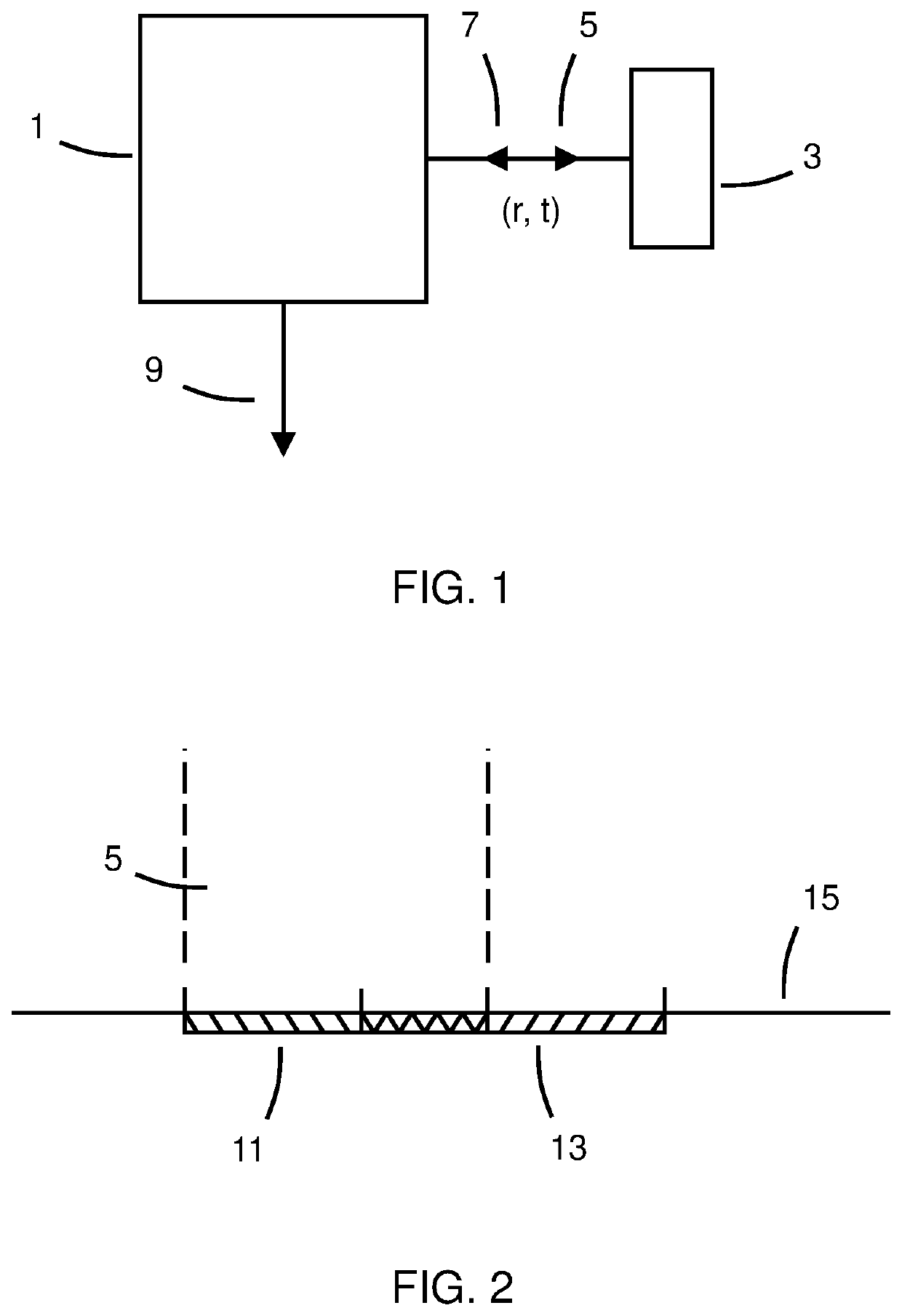
[0043]FIG. 1 schematically illustrates an example of an apparatus 1. The apparatus 1 causes illumination of different areas 11, 13 (see FIG. 2 below) of a sample 3 with an imaging beam 5 at different positions (r) at different times (t). Of these different positions, adjacent positions are configured to cause the corresponding areas 11, 13 to at least partially overlap. The adjacent positions may be directly adjacent to one another. The adjacent positions may be contiguous.

[0044]In the illustrated example, the imaging beam 5 is coherent and comprises a plurality of wavefronts which have a fixed phase relationship for a period of time. For example, the fixed phase relationship is maintained at least over a period of time between emission from a source until incidence upon a sensor. Photons comprised in the imaging beam 5 may thus have a fixed phase relationship over the time required for imaging. The imaging beam 5 may, for example, be comprised of light emitted by a laser.

[0045]In s...


PUM


Abstract

An apparatus comprising means for: causing illumination of different areas of a sample with an optical frequency imaging beam at different positions at different times, wherein adjacent positions are configured to cause the corresponding areas to at least partially overlap;receiving signals indicative of back-scattering of the optical frequency imaging beam from the sample at the different times; and processing the received signals to obtain an image of the sample, wherein processing the received signals compensates for phase variations between the different positions at the different times using a matched filter derived from a scattering model of the sample.

Description

TECHNOLOGICAL FIELD[0001]Embodiments of the present disclosure relate to apparatus, methods, and computer programs for obtaining an image of a sample. Some relate to apparatus, methods, and computer programs for obtaining an image estimating an internal structure of a sample.BACKGROUND[0002]Image resolution is related to aperture size. Increasing the size of an aperture causes improved resolution of images of objects at the associated focal depth. Increasing the size of the aperture also increases the rate of image resolution degradation with depth-wise displacement of objects from the focal depth. Mechanical readjustment of the focal depth may be used to image a three-dimensional scene with acceptable image resolution across a range of depths in the scene.BRIEF SUMMARY[0003]According to various, but not necessarily all, embodiments there is provided an apparatus comprising means for: causing illumination of different areas of a sample with an optical frequency imaging beam at diffe...

Claims


Application Information

Patent Timeline
Patent Type & Authority Applications(United States)
IPC IPC(8): G01B9/02
CPCG01B9/02091G01B9/02085G01B2210/28G01B2210/52G01B9/02004G01B9/02075G01B9/0209G01S17/90
Inventor KANEDA, NORIAKIEGGLESTON, MICHAEL
Owner NOKIA TECHNOLOGLES OY
Learn More