
A heliostat sub-assembly

a technology of heliostats and sub-assemblies, which is applied in the direction of heat collector mounting/supports, lighting and heating apparatus, instruments, etc., can solve the problems of glue taking some time to cure fully, and the manufacturing process of lightweight steel frames of these dimensions is difficult, so as to facilitate the alignment of faces

Pending Publication Date: 2022-02-24
VAST SOLAR PTY
View PDF11 Cites 0 Cited by
  • Summary
  • Abstract
  • Description
  • Claims
  • Application Information

AI Technical Summary

Benefits of technology

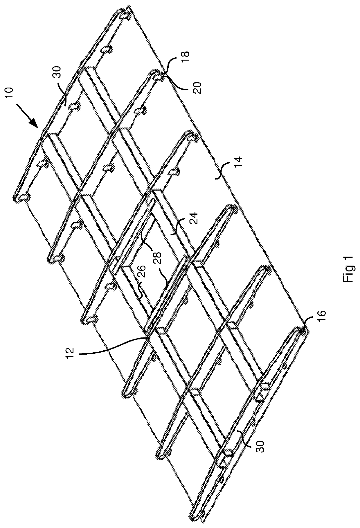
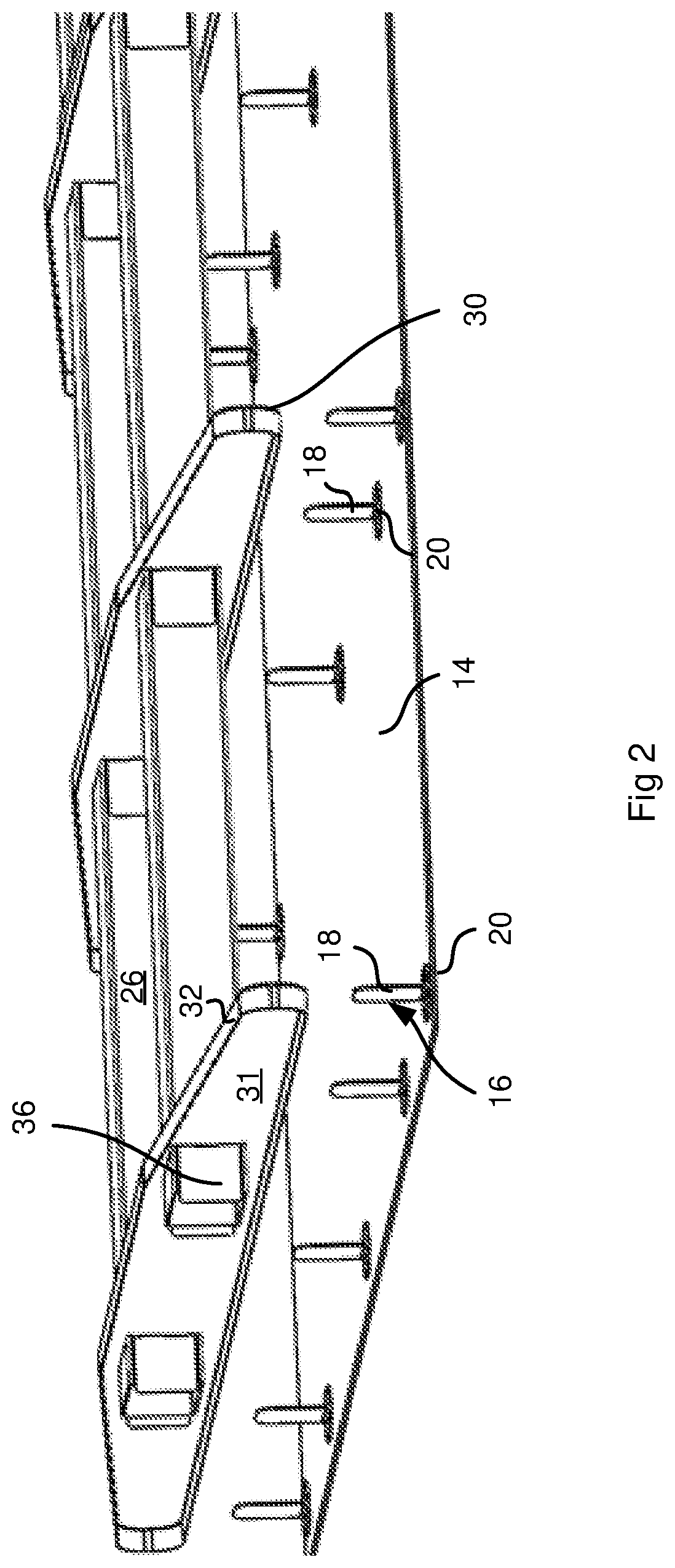
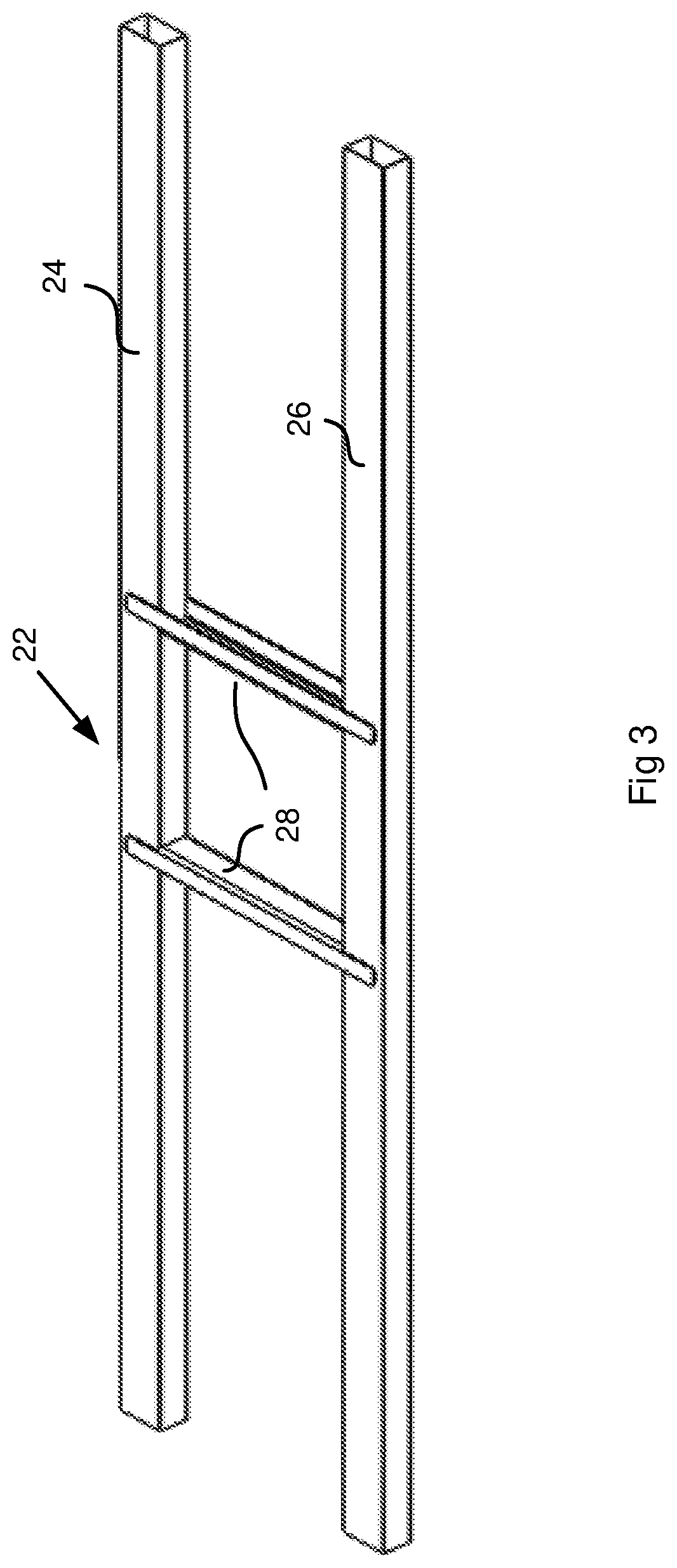
The patent text describes a heliostat riser sub-assembly used to connect a curved heliostat mirror to a support frame. The sub-assembly includes a riser pad for bonding to the mirror, a riser stem with a tab portion for connection to the frame, and a multi-axial joint assembly that allows limited movement of the stem relative to the bonding pad to align the tab portion with the frame. The technical effects of this invention include improved alignment accuracy and flexibility during installation, allowing for a more precise and reliable connection between the mirror and support frame.

Problems solved by technology

To manufacture a lightweight steel frame of these dimensions which is capable of holding a mirror within a few millimetres of flatness is a difficult process, in particular where post-manufacturing processes of hot dipped galvanising are included.
This is also problematic in that the glue takes some time to cure fully, and that the jig has to hold the glass in a deformed state until the glue has fully cured.

Method used


Image

  • A heliostat sub-assembly
  • A heliostat sub-assembly
  • A heliostat sub-assembly

Examples


first embodiment

[0059]Once the riser sub-assemblies 40 have cured and are firmly bonded to the inner face of the mirror 14A, the outer face of the mirror is bent to the desired parabolic shape over a forming jig or die with an adjustable parabolic curve in the z-plane about both the x-and y-axes in the manner previously described with reference to the It should be noted that while the desired shape of the final mirror and frame after the jig is removed is paraboloid or spherical / spheroid the jig may need to move the mirror into a slightly different shape so that it relaxes into the desired final shape after the jig is removed and the load is taken up by the glue and the frame.

[0060]Referring now to FIG. 9, a frame 86 is shown being lowered towards the rear face of the mirror 14A and riser sub-assemblies 40, with the mirror being bent to the desired shape over the forming jig (not shown). The frame 86 includes four equi-spaced purlins or ribs 88 having a U-shaped profile terminating in outwardly fl...

second embodiment

[0062]An advantage of the second embodiment is that it provides small amounts of play that allow the riser tabs to rotate a little from being perfectly normal to the mirror, and allow the foot portion of the riser tabs to slide a little parallel to the mirror. This allows the risers to be fixed to a frame that has a different coefficient of thermal expansion than the glass. Changes in temperature therefore allow the frame to expand parallel to the glass without building up stresses in the glass, while retaining the frame's ability to provide precise location of the glass in the direction orthogonal to the plane of the glass. Similarly the pin rotation or universal canting ability allows the glass to be slightly curved to generate the focusing shape desirable for the mirror, and allows the small relative rotation of the pin to accommodate this rotation without placing rotational stress on the glued pad.

[0063]In some embodiments clinching jigs may also be used to clinch the riser stem...


PUM


Abstract

The invention relates to a heliostat sub-assembly and to a method of forming such a sub-assembly. The method of mounting a concave mirror to a supporting structure of a heliostat includes the steps of bonding a plurality of risers at predetermined spaced intervals to a rear face of the mirror, each riser having a bonding pad and a stem extending from the bonding pad, and applying a predetermined concave curvature to the mirror by conforming the front face of the mirror with a convex forming jig or die. The supporting structure and curved mirror are then aligned, and the supporting structure is clinched to the stems of the risers when the curved mirror is conformed with the forming die. The riser stems may be coupled to the bonding pads via multi-axial joint assemblies to enable limited multi-pivotal movement of the stems relative to the bonding pads to facilitate alignment of faces of the stems with the faces of the ribs defined by webs, and relative expansion and contraction of the mirror and supporting structure, the overlap between the riser stems and the webs being sufficient to accommodate clinching with variations in curvature of the glass sheet.

Description

FIELD OF THE INVENTION[0001]This invention relates to a heliostat sub-assembly and to a method of forming such a sub-assembly.BACKGROUND OF THE INVENTION[0002]Heliostats are typically used in the area of concentrating solar power (CSP) to redirect sunlight onto a focal point provided by a receiver on a central tower. The heliostats are typically arranged in a series of arcs around the tower at distances typically varying from 30 m to 250 m or more. Each heliostat generally includes a concave mirror with focal length corresponding to the distance between the mirror and the receiver and a support structure to hold the mirror.[0003]The support structure may include a support frame to which the mirror is mounted and a ground-engaging stand or post arrangement which is mounted to the frame in a manner which allows the mirror to be articulated with two degrees of rotational freedom so that the sun can be tracked to maintain the focal point of the mirror on the receiver. Larger heliostats ...

Claims


Application Information

Patent Timeline
Patent Type & Authority Applications(United States)
IPC IPC(8): F24S23/70F24S23/74G02B7/183G02B5/10G02B7/182G02B7/198
CPCF24S23/82F24S23/74G02B7/183F24S2025/014G02B7/1821G02B7/198G02B5/10F24S2025/6009F24S2025/601F24S2025/6013F24S2025/806Y02E10/40G02B7/1827
Inventor DREWES, KURT FRIEDRICHLESLIE, BRUCE ALEXANDER
Owner VAST SOLAR PTY
Learn More