
Touch display device

Active Publication Date: 2022-02-10
TPK TOUCH SOLUTIONS (XIAMEN) INC
View PDF0 Cites 0 Cited by
  • Summary
  • Abstract
  • Description
  • Claims
  • Application Information

AI Technical Summary

Benefits of technology

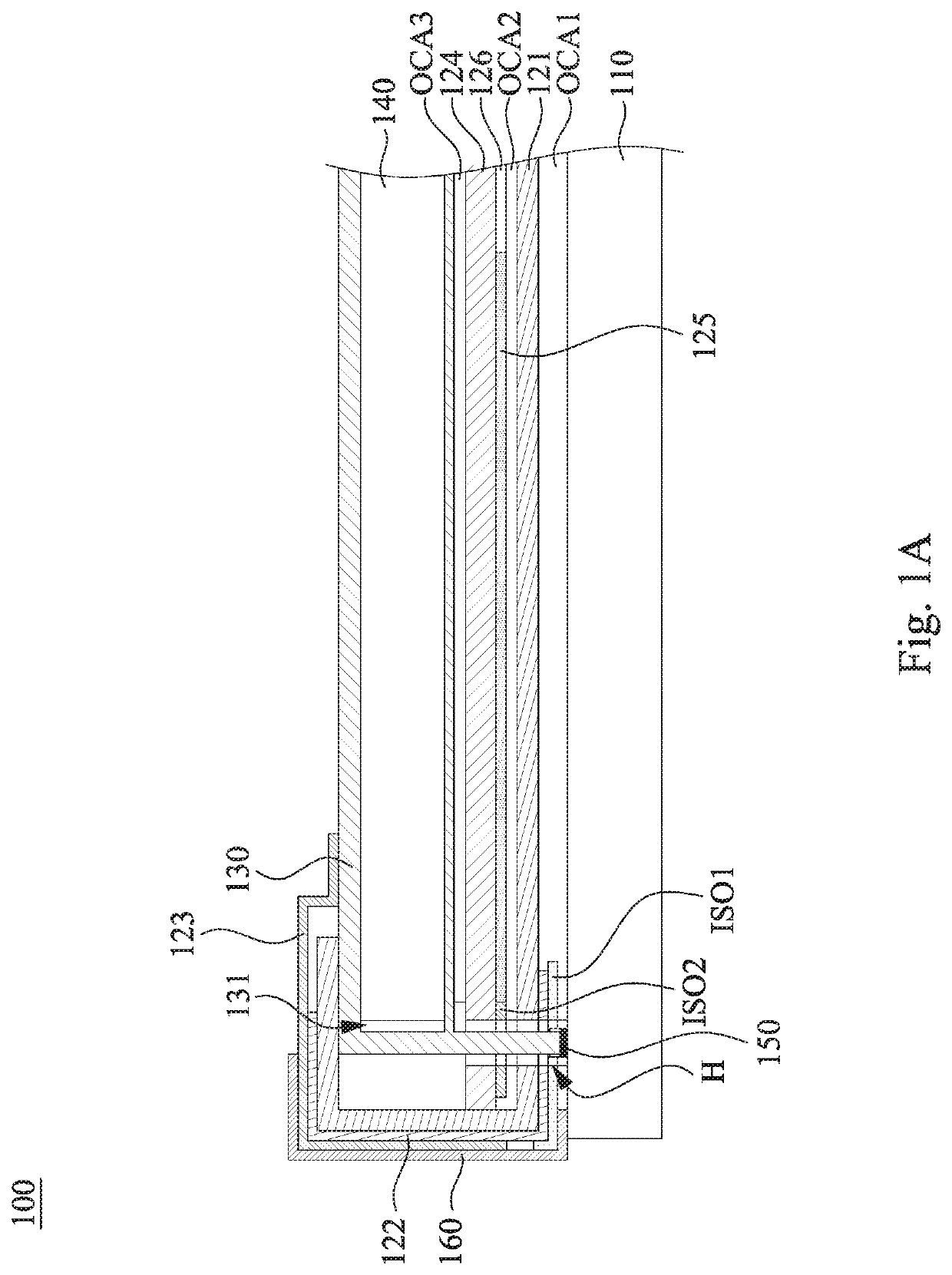
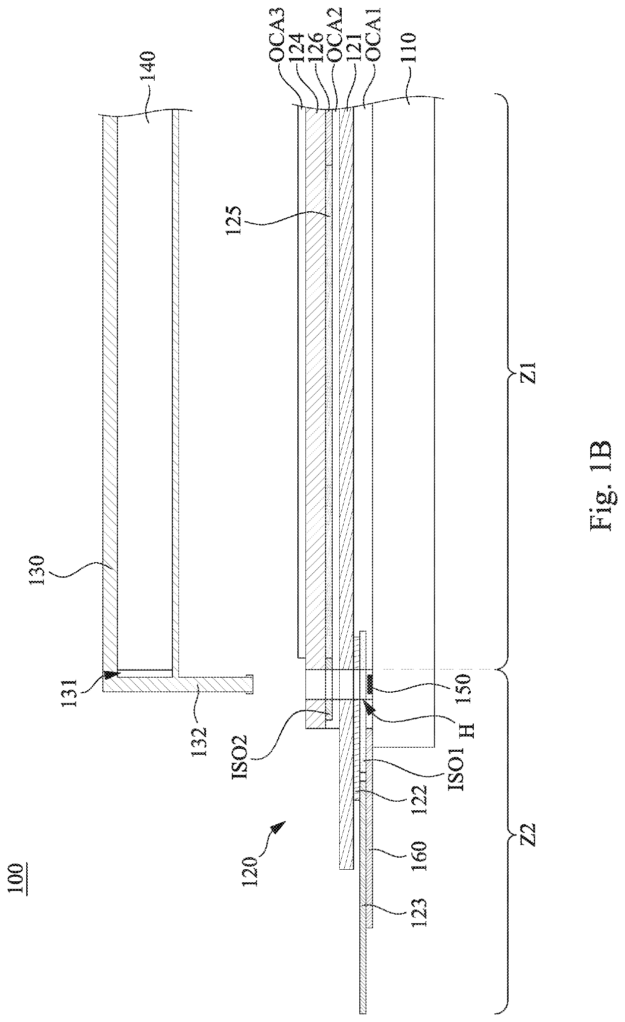
The present invention provides a touch display device that solves the problem of inefficient assembly of the touch module and display module. By arranging fixing members on the frame and making them cross the peripheral zone outside the sensing zone of the touch panel to be fixed to the cover plate, the assembled structure of the touch module and display module of large-size achieves sufficient bearing strength.

Problems solved by technology

Therefore, it is difficult for the cover plate to be stably fixed and assembled on the display panel by only relying on a layer of OCA.

Method used


Image

  • Touch display device
  • Touch display device
  • Touch display device

Examples


Embodiment Construction

[0022]Reference will now be made in detail to the present embodiments of the disclosure, examples of which are illustrated in the accompanying drawings. Wherever possible, the same reference numbers are used in the drawings and the description to refer to the same or like parts. However, specific structural and functional details disclosed herein are merely representative for purposes of describing example embodiments, and thus may be embodied in many alternate forms and should not be construed as limited to only example embodiments set forth herein. Therefore, it should be understood that there is no intent to limit example embodiments to the particular forms disclosed, but on the contrary, example embodiments are to cover all modifications, equivalents, and alternatives falling within the scope of the disclosure.

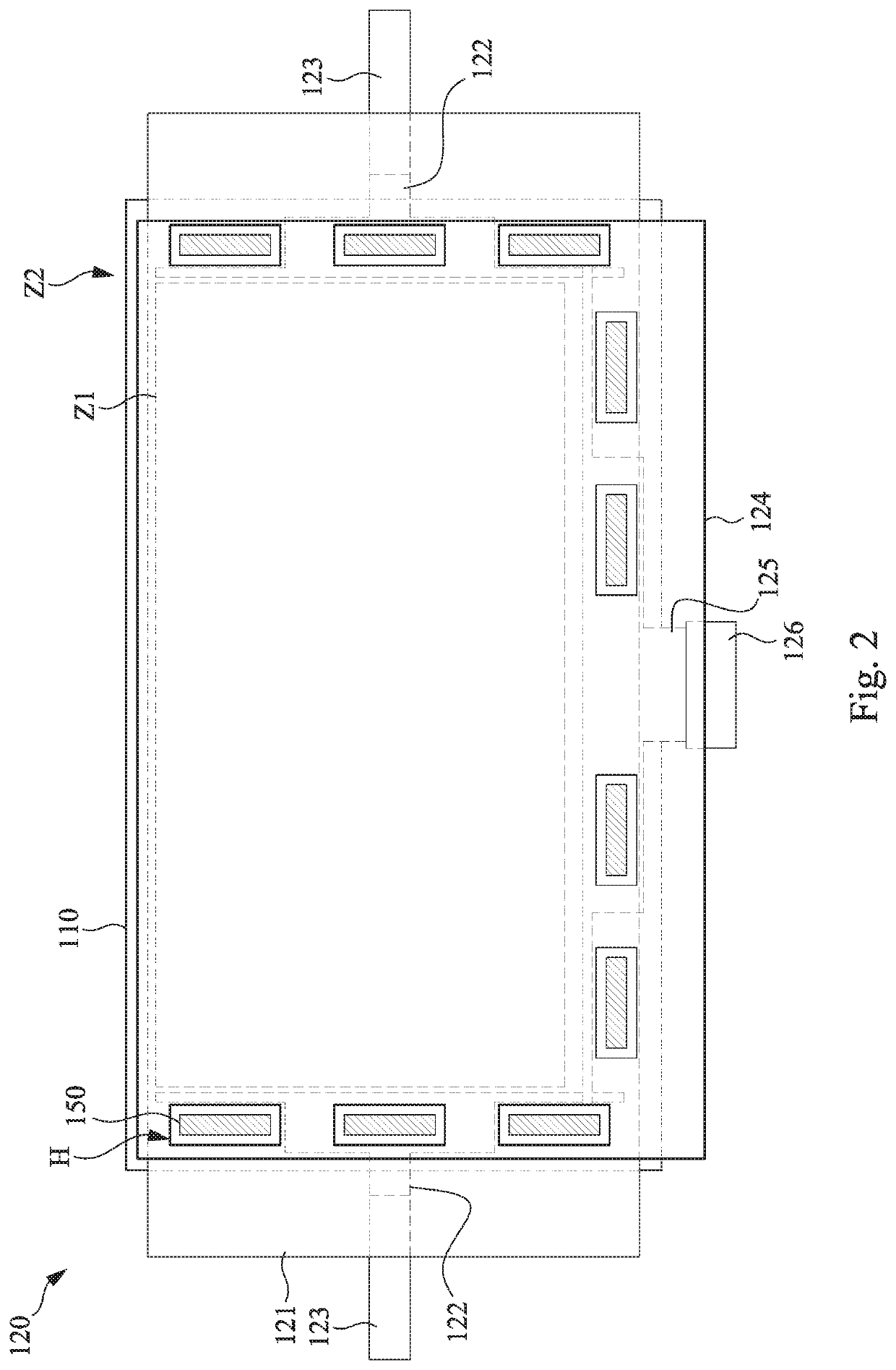
[0023]Reference is made to FIGS. 1A and 1B. FIG. 1A is a cross-sectional view of a touch display device 100 according to an embodiment of the disclosure. FIG. 1B is anothe...


PUM


Abstract

A touch display device includes a cover plate, a touch module, a frame, and a display module. The touch module is disposed on the cover plate and defines thereon a sensing zone and a peripheral zone connecting each other. The frame is located at a side of the touch module away from the cover plate and includes a plurality of fixing members and an accommodating trough. The fixing members cross the peripheral zone to be fixed to the cover plate. At least one part of the touch module in the peripheral zone is attached to a side of the frame away from the cover plate. The display module is disposed in the accommodating trough and over the sensing zone.

Description

BACKGROUNDTechnical Field[0001]The present disclosure relates to a touch display device.Description of Related Art[0002]A current goal of a narrow border touch display device is mainly to minimize the width of the border (BM area) of the touch panel. The specific approach is that after the touch panel and the display panel are fully bonded, a part of the touch panel that extends beyond the sensing zone is bent along the non-bonding zone on the outer edge of the display panel to the back of the display panel and then fixed by adhesive.[0003]In order to achieve a narrow border for a touch display device, the cover plate and the display panel are usually fixed and assembled together by only relying on optically clear adhesive (OCA). However, when manufacturing a large-size touch display device (e.g., a touch panel over 55 inches), considering the yield and convenience of assembly, the cover plates must have a certain thickness and weight to maintain a certain degree of toughness. There...

Claims


Application Information

Patent Timeline
IPC IPC(8): G06F3/041
CPCG06F3/0412G06F2203/04103G06F3/04164
Inventor SHIH, HSUEH-HANWANG, YING-FUHUANG, CHUN JUNGLIN, SHANG-YUTANG, CHI
Owner TPK TOUCH SOLUTIONS (XIAMEN) INC
Learn More