
Connector

Active Publication Date: 2021-06-03
FMC TECH DO BRASIL
View PDF0 Cites 0 Cited by
  • Summary
  • Abstract
  • Description
  • Claims
  • Application Information

AI Technical Summary

Benefits of technology

The present invention provides contact surfaces with specific angles and spacing that improve tension uniformity. This combination of features creates a more efficient solution for achieving even tension distribution. This invention ensures better sizing and optimization of connector projects by making the tension distribution more uniform.

Problems solved by technology

Equal angles generate a non-uniform tension distribution on the contact surfaces due to the non-uniform stiffness distribution to the components.

Method used


Image

  • Connector
  • Connector
  • Connector

Examples


Embodiment Construction

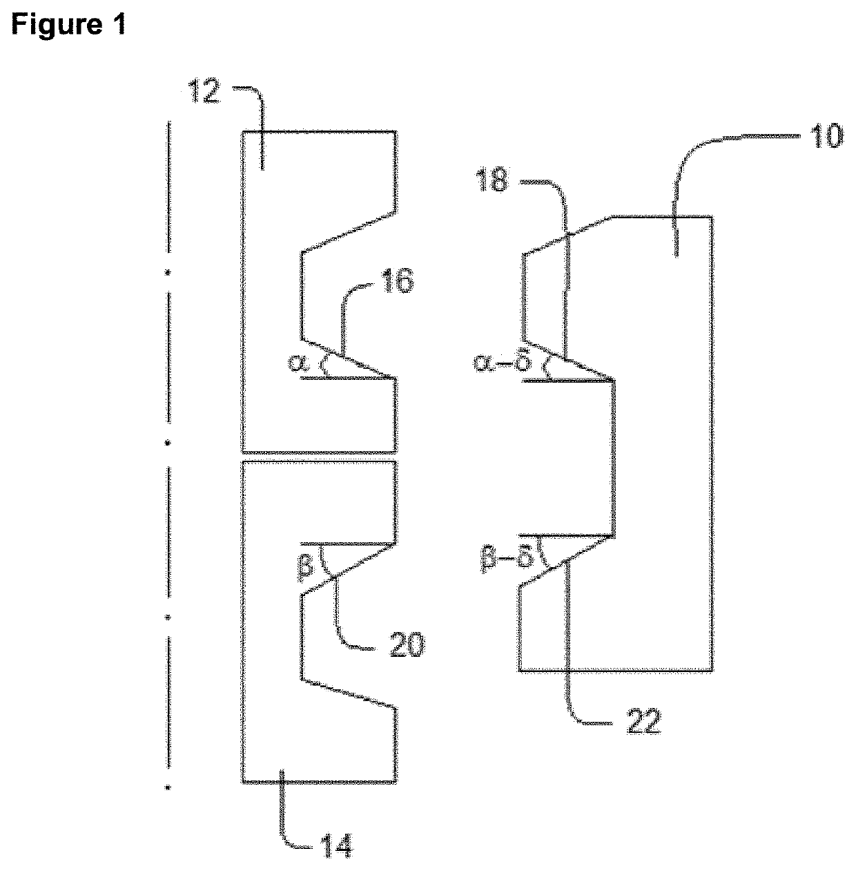
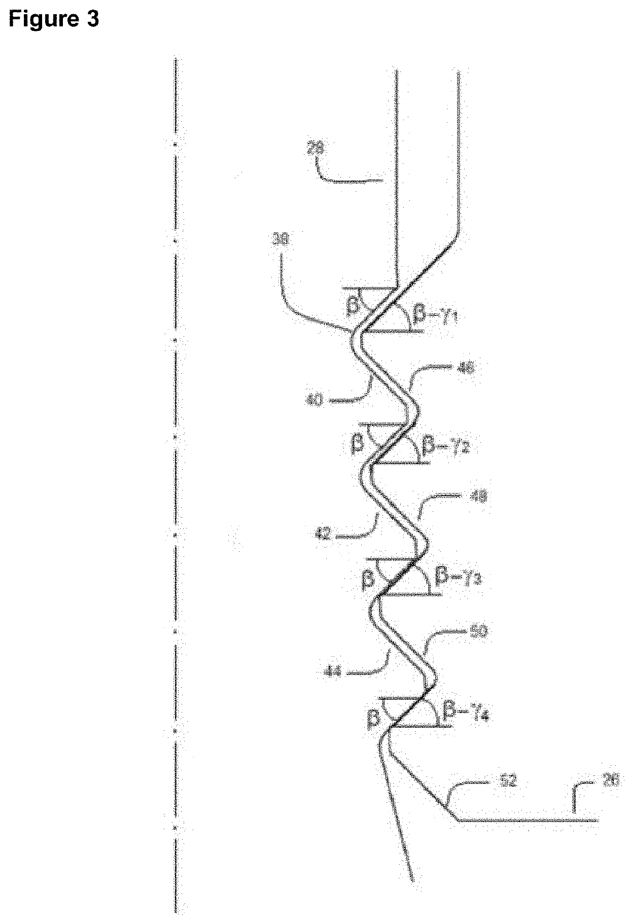
[0019]The present invention relates to a connector comprising a jaw (26) having a configuration to better distribute tensions on the contact surfaces of the teeth, i.e., it has contact surfaces with differentiated angles and differentiated spacings, conferring an extremely beneficial effect on the tension uniformity on the contact surfaces, solving the problem regarding the non-uniformity of the tension distribution on the teeth contact surfaces, and of the connectors in general, since the stiffness distribution of these teeth is also not uniform as well as the stiffness distribution in the wellhead is not uniform.

[0020]FIG. 1 shows schematically a jaw (10) connecting a connection element (12) and a wellhead (14). This jaw (10) comprises teeth (18) and (22) having angles different from the angles of the tooth (16) of the connection element (12) and different from the angle of the tooth (20) of the hub (14). The number of teeth of the jaw varies from one to four but is not limited to...


PUM


Abstract

A connector includes a jaw used to connect a connection element and a wellhead designed to better distribute tensions on the contact surfaces of the teeth thereof, including, for example, having contact surfaces with differentiated angles and differentiated spacing, resulting evened tensions on the contact surfaces of the teeth.

Description

FIELD OF THE INVENTION[0001]The present invention relates to a wellhead connector having a teeth configuration that allows a more uniform tension distribution between male and female. Such a configuration consists of a jaw profile comprising a differentiated spacing among teeth and differentiated teeth angles (between male and female). The present invention can be used on contact surfaces, through which the preload of connectors of any type, from terrestrial to subsea connectors, passes.BACKGROUND OF THE INVENTION[0002]Connectors are used to connect two types of equipment, usually cylindrical parts, and apply a certain preload therebetween. Therefore, connectors are commonly used in the oil and gas field, for example, by connecting the wellhead to the BOP.[0003]The connector is made up of multi-toothed jaws having a tooth profile that is used to apply a preload to the contact surface. Despite the male (connector jaw) and female (wellhead contact surface) have the same profile in ord...

Claims


Application Information

Patent Timeline
IPC IPC(8): E21B33/038
CPCE21B33/038F16L37/08
Inventor ANDUEZA, ALEJANDRO
Owner FMC TECH DO BRASIL
Learn More