Moon-based in-situ condition-preserved coring multi-stage large-depth drilling system and method therefor

Pending Publication Date: 2022-02-10
SHENZHEN UNIV +1
View PDF0 Cites 2 Cited by
  • Summary
  • Abstract
  • Description
  • Claims
  • Application Information

AI Technical Summary

Benefits of technology

The present disclosure is a multi-stage large-depth drilling system and method for moon-based in-situ condition-preserved coring. The technical effects of this patent include solving the problem of coring the lunar soil, collecting, excavating and transporting the lunar soil in an in-situ condition-preserved state, and increasing the sampling amount of the lunar soil coring. This is achieved by controlling the mechanical arm to place the in-situ condition-preserved coring tool on the moon surface, and using the tool to sample soil, rocks, and more on the moon surface.

Problems solved by technology

Unlike a conventional land-based drilling activity, a lunar drilling activity faces a number of challenges.

Method used


Image

  • Moon-based in-situ condition-preserved coring multi-stage large-depth drilling system and method therefor
  • Moon-based in-situ condition-preserved coring multi-stage large-depth drilling system and method therefor
  • Moon-based in-situ condition-preserved coring multi-stage large-depth drilling system and method therefor

Examples


embodiment 1

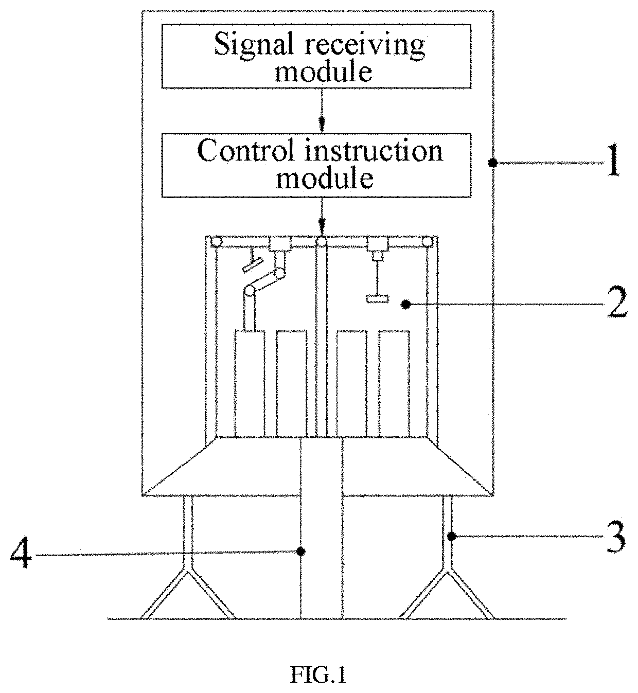
[0038]As shown in FIG. 1, FIG. 1 illustrates a schematic diagram of a lander 1 in the present embodiment.

[0039]In the present embodiment, when the lander 1 lands on moon surface, the lander 1 is supported by a frame base 3 at a bottom of the lander 1. When excavating a soil on the moon surface is required, the lander 1 performs an exploration through a coring channel 4 at the bottom of the lander 1. The lander 1 has a signal receiving module and a control instruction module arranged thereon. The signal receiving module is configured to receive a signal transmitted from a launch base before converting the signal into a digital control program. The digital control program after conversion controls a moon-based in-situ condition-preserved coring multi-stage large-depth drilling system 2 inside the lander 1 to operate, by a control instruction output from the control instruction module.

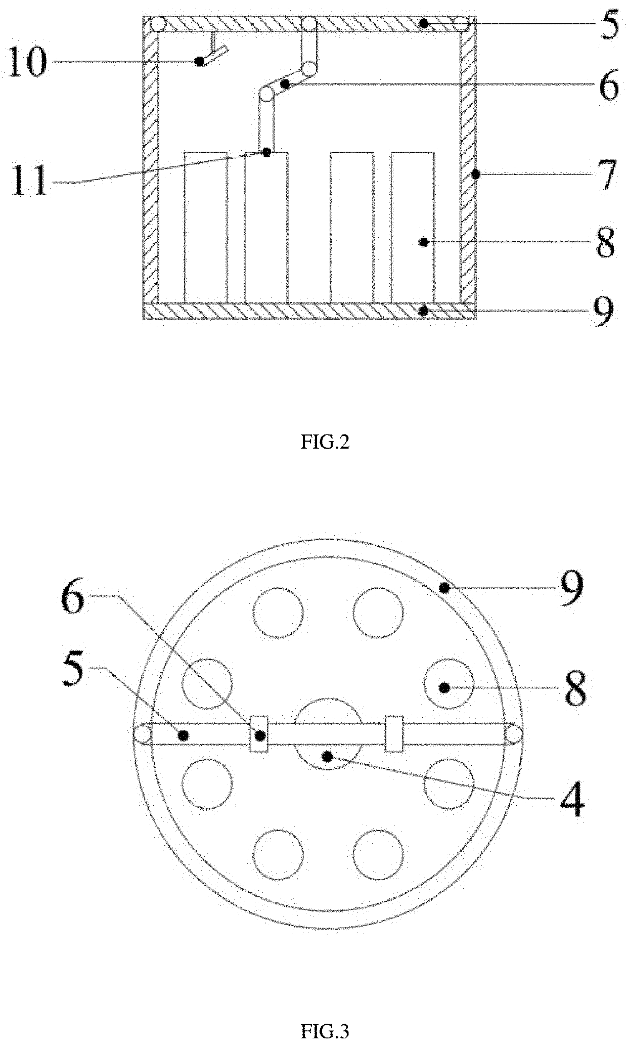
[0040]As shown in FIG. 2 and FIG. 3, the moon-based in-situ condition-preserved coring multi-stage lar...

embodiment 2

[0069]The present embodiment provides a moon-based in-situ condition-preserved coring multi-stage large-depth drilling method, as shown in FIG. 5, comprising steps of:

[0070]Step 100: Controlling a mechanical arm to grab an in-situ condition-preserved coring tool from a rotary plate and place the in-situ condition-preserved coring tool on moon surface when a lander receives a drilling signal transmitted from a launch base. Detailed information is stated hereinabove.

[0071]Step 200: Acquiring a signal output from a hardness sensor when the mechanical arm places the in-situ condition-preserved coring tool on the moon surface, and judging whether a hardness of a lunar soil on the moon surface meets a sampling standard according to the signal. Detailed information is stated hereinabove.

[0072]Step 300: Controlling a motor driving mechanism in the in-situ condition-preserved coring tool to operate when the hardness of the lunar soil on the moon surface meets the sampling standard, and using...


PUM


Abstract

A moon-based in-situ condition-preserved coring multi-stage large-depth drilling system and method therefor. The system includes a rotary plate provided inside a lander, an in-situ condition-preserved coring tool provided on a surface of the rotary plate, a space frame provided on a surface of the rotary plate, a working platform provided on a top of the space frame, a mechanical arm provided on a bottom surface of the working platform, and a camera provided on the bottom surface of the working platform, the mechanical arm is fixedly connected to the working platform, and the camera is fixedly connected to the working platform. By controlling the mechanical arm to place the in-situ condition-preserved coring tool on the moon surface, and using the in-situ condition-preserved coring tool to sample the lunar soil on the moon surface, the coring operation problem of the lunar soil is solved.

Description

FIELD OF THE DISCLOSURE[0001]The present disclosure relates to the technical field of moon exploration, and more particularly, to a multi-stage large-depth drilling system and method for moon-based in-situ condition-preserved coring.BACKGROUND[0002]Deep space exploration is an inevitable direction for future development, and the Moon is a celestial body closest to our mankind. The Moon is rich in a plurality of mineral resources including iron, titanium and uranium, as well as the famous helium-3 gas energy source. A sample from lunar surface can be regarded as priceless. Therefore, moon drilling is of a great strategic significance for a plurality of problems including researching a material composition of the lunar surface, an origin of the moon, a phenomenon of the Earth climate and tidal flood, and a plurality of resources in future.[0003]Unlike a conventional land-based drilling activity, a lunar drilling activity faces a number of challenges. Due to an effect of a plurality of...

Claims


Application Information

Patent Timeline
IPC IPC(8): E21B25/00E21B49/02E21B6/02E21B19/086
CPCE21B25/00E21B19/086E21B6/02E21B49/02G01N1/08G01N1/04G01V8/10G01N3/40G01N2203/0076G01N2203/0244E21C51/00
Inventor XIE, HEPINGGAO, MINGZHONGCHEN, LINGZHANG, GUOQINGLI, JIANANZHU, JIANBOLI, CUNBAO
Owner SHENZHEN UNIV
Why Eureka
Try Eureka