Three-dimensional shaping device, method for manufacturing three-dimensional shaped object, and information processing device

a three-dimensional shape and information processing technology, applied in the direction of additive manufacturing processes, manufacturing tools, instruments, etc., can solve problems such as affecting shaping accuracy

Active Publication Date: 2022-02-03
SEIKO EPSON CORP
View PDF8 Cites 0 Cited by
  • Summary
  • Abstract
  • Description
  • Claims
  • Application Information

AI Technical Summary

Benefits of technology

[0005]According to a first aspect of the present disclosure, there is provided a three-dimensional shaping device that shapes a three-dimensional shaped object by laminating a layer. The three-dimensional shaping device includes: an ejection unit configured to eject a shaping material toward a table; a measurement unit configured to measure the shaping material at a measurement position separated from an ejection position of the ejection unit by a predetermined distance; a position changing unit configured to relatively move the ejection position and the measurement position with respect to the table; and a control unit. A movement range in which the measurement position is moved is wider than a shaping region where the shaping material is deposited on the table. The control unit is configured to perform a measurement of a measurement value by the measurement unit at least in a region where the movement range and the shaping region overlap each other, and control the ejection unit and the position changing unit to shape the three-dimensional shaped object in accordance with the measurement value.

Problems solved by technology

Therefore, there is a difference between a region where the shaping material is ejected from the ejection unit and a region where the temperature is measured by the thermometer, which may affect shaping accuracy.
Such a problem is a common problem not only in a three-dimensional shaping device in which a material is heated after being ejected as in JP-A-2017-43805, but also in a three-dimensional shaping device in which a pre-melted material is ejected from an ejection unit.

Method used


Image

  • Three-dimensional shaping device, method for manufacturing three-dimensional shaped object, and information processing device
  • Three-dimensional shaping device, method for manufacturing three-dimensional shaped object, and information processing device
  • Three-dimensional shaping device, method for manufacturing three-dimensional shaped object, and information processing device

Examples


first embodiment

A. First Embodiment

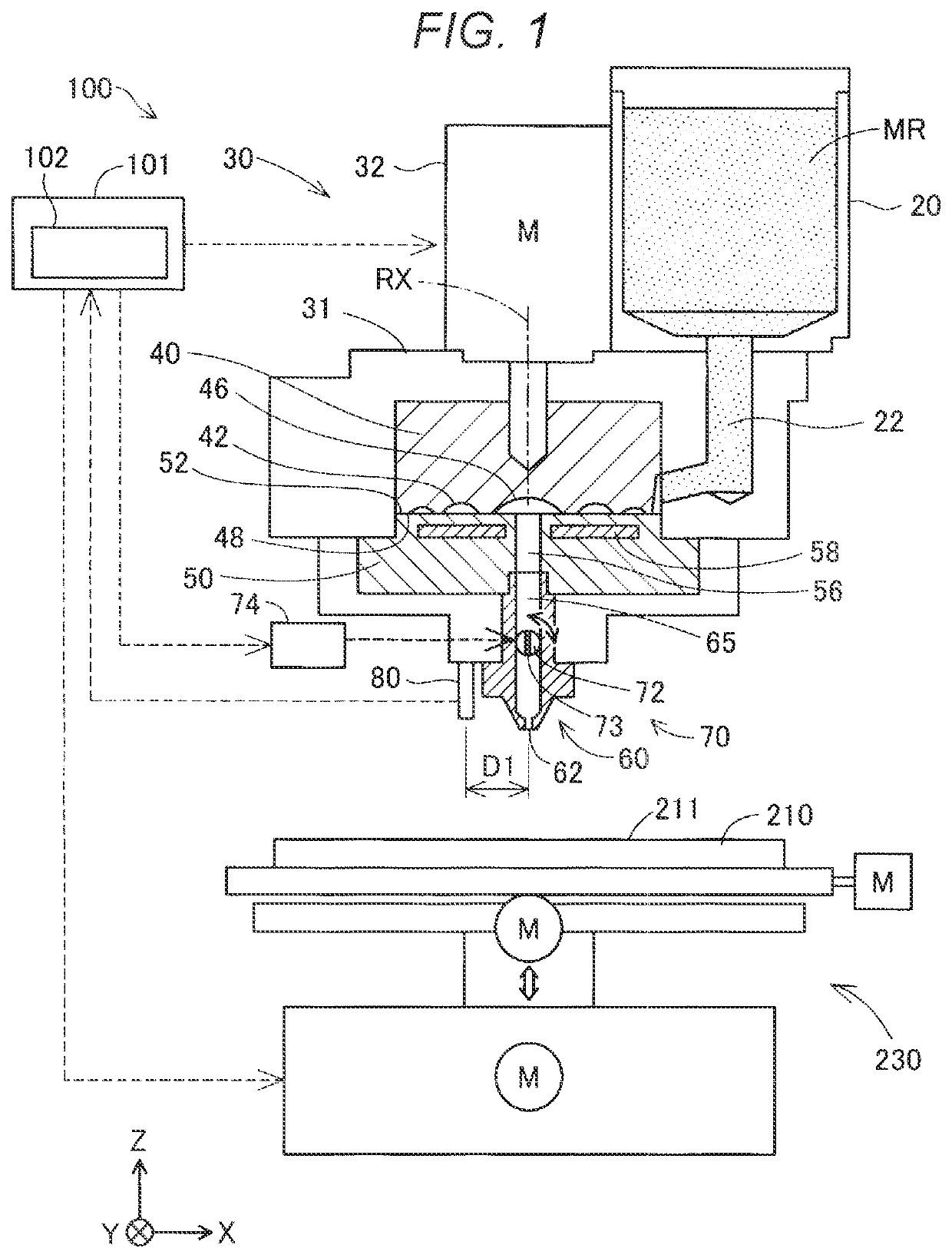
[0020]FIG. 1 is an explanatory diagram showing a schematic configuration of a three-dimensional shaping device 100 according to a first embodiment. FIG. 1 shows arrows indicating X, Y, and Z directions that are orthogonal to one another. The X direction and the Y direction are directions parallel to a horizontal plane, and the Z direction is a direction opposite from a direction of gravity. The arrows indicating the X, Y, and Z directions are also appropriately shown in other figures such that the shown directions correspond to those in FIG. 1. In the following description, when a direction is specified, “+” indicates a positive direction and “−” indicates a negative direction, and positive and negative symbols are used together to indicate directions.

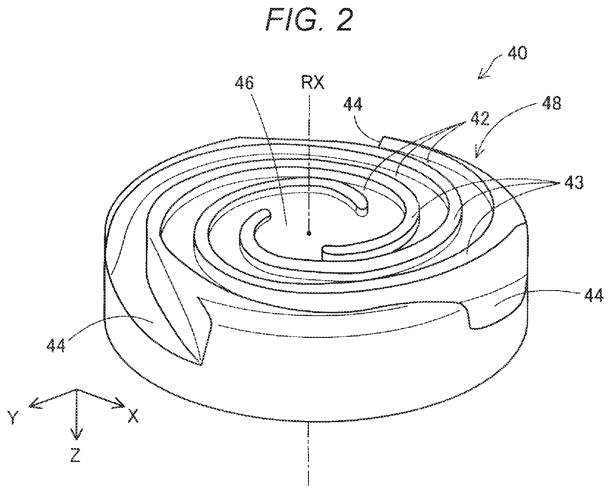
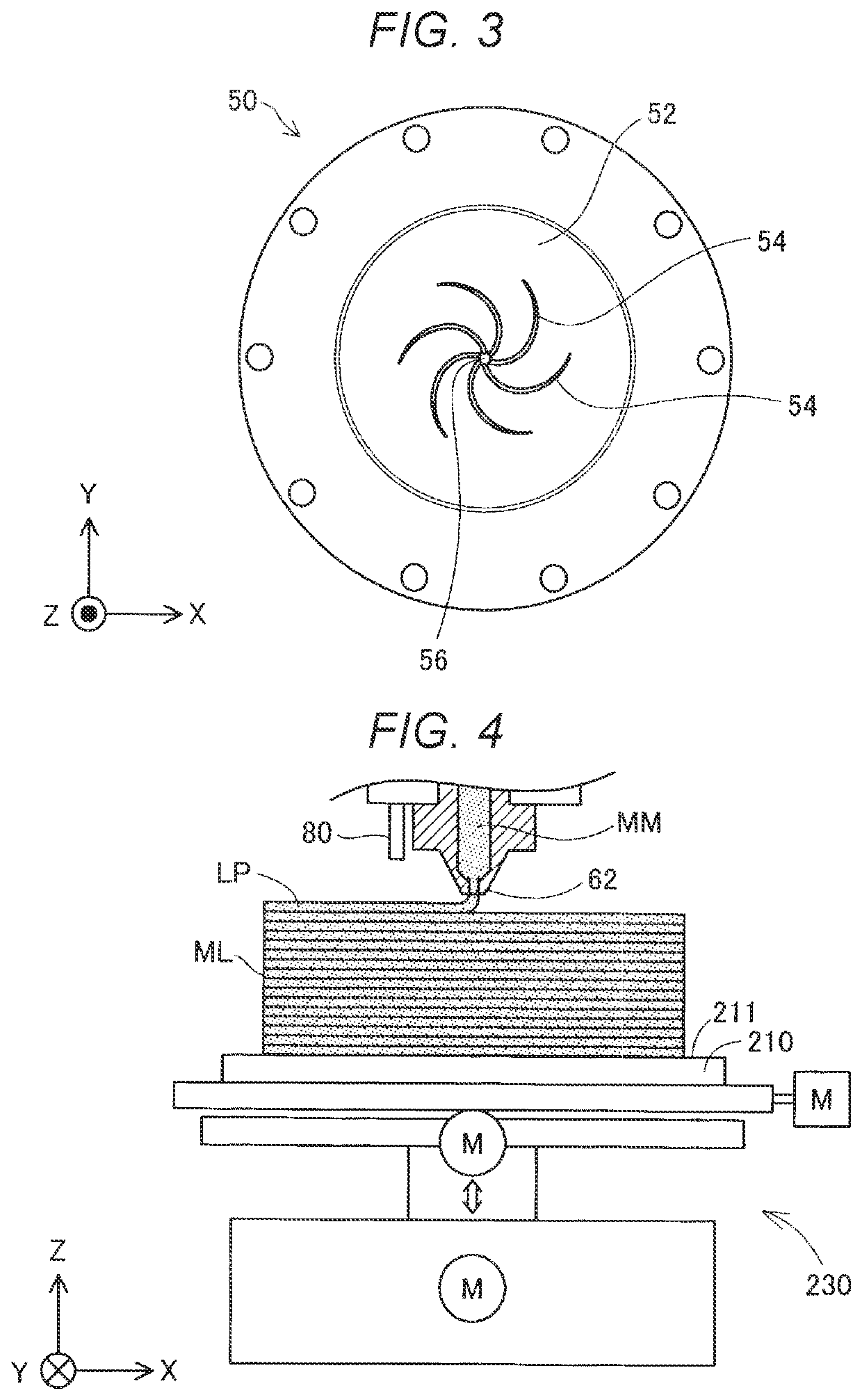
[0021]The three-dimensional shaping device 100 is a device that shapes a three-dimensional shaped object by laminating layers. The three-dimensional shaping device 100 includes: a table 210 for shaping which is a bas...

second embodiment

B. Second Embodiment

[0073]In the first embodiment described above, the measurement unit 80 is provided on a −X direction side of the nozzle 62. In contrast, in a second embodiment, the measurement unit 80 is provided so as to be rotatable around the nozzle 62.

[0074]FIG. 12 is a view of the nozzle 62 and the measurement unit 80 according to the second embodiment when viewed from a table 210 side in a +Z direction. In the present embodiment, the measurement unit 80 is attached to a ring-shaped rotating body 85, which is rotatable around the nozzle 62, at a position separated from the nozzle 62 by the distance D1. The rotating body 85 is rotated by a drive motor (not shown) coupled by a gear or a belt. A rotation operation of the measurement unit 80 performed by the rotating body 85 is controlled by the control unit 101 controlling the drive motor coupled to the rotating body 85. The rotating body 85 itself may be configured as a ring-shaped motor.

[0075]In the present embodiment, the c...


PUM

PropertyMeasurementUnit
shapesaaaaaaaaaa
timeaaaaaaaaaa
distanceaaaaaaaaaa

Abstract

There is provided a three-dimensional shaping device that shapes a three-dimensional shaped object by laminating a layer. The three-dimensional shaping device includes: an ejection unit configured to eject a shaping material toward a table; a measurement unit configured to measure the shaping material at a measurement position separated from an ejection position of the ejection unit by a predetermined distance; a position changing unit configured to relatively move the ejection position and the measurement position with respect to the table; and a control unit. A movement range in which the measurement position is moved is wider than a shaping region where the shaping material is deposited on the table. The control unit is configured to perform a measurement of a measurement value by the measurement unit at least in a region where the movement range and the shaping region overlap each other, and control the ejection unit and the position changing unit to shape the three-dimensional shaped object in accordance with the measurement value.

Description

[0001]The present application is based on, and claims priority from JP Application Serial Number 2020-127823, filed Jul. 29, 2020, the disclosure of which is hereby incorporated by reference herein in its entirety.BACKGROUND1. Technical Field[0002]The present disclosure relates to a three-dimensional shaping device, a method for manufacturing a three-dimensional shaped object, and an information processing device.2. Related Art[0003]In a three-dimensional shaping device described in JP-A-2017-43805, a lamp that radiates heat is provided on a lamp support portion so as to evaporate a liquid component of a shaping material ejected from an ejection unit. The lamp support portion is provided with a non-contact type thermometer together with the lamp, and a temperature of a heating region of the lamp is measured. The three-dimensional shaping device controls electric power to be supplied to the lamp such that the temperature measured by the thermometer is a predetermined temperature.[000...

Claims


Application Information

Patent Timeline
Patent Type & Authority Applications(United States)
IPC IPC(8): B29C64/393B29C64/236B29C64/165B29C64/321
CPCB29C64/393B29C64/236B33Y10/00B29C64/321B29C64/165B29C64/106B29C64/20B29C64/386B22F10/22B22F10/80B22F10/85B28B1/001B28B17/0081B33Y30/00B33Y50/00B33Y50/02B29C64/118B29C64/209B22F10/18B22F12/53B22F12/90B22F12/224G01B11/00G01B11/02Y02P10/25
Inventor YAMAZAKI, SHIGERU
Owner SEIKO EPSON CORP
Why Eureka
Try Eureka