Eureka AIR delivers breakthrough ideas for toughest innovation challenges, trusted by R&D personnel around the world.

Hybrid spinal cages, systems and methods

a spinal cage and hybrid technology, applied in the field of medical devices, can solve the problems of insufficient disc thickness and/or support to absorb, degenerated disc b>8/b> having decreased thickness, and limit the ability, and achieve the effect of enhancing bone ingrowth

Pending Publication Date: 2022-02-03
CTL MEDICAL CORP
View PDF0 Cites 3 Cited by
  • Summary
  • Abstract
  • Description
  • Claims
  • Application Information

AI Technical Summary

Benefits of technology

The patent describes a cage structure for spine implants that can be made of different materials and textures. The cage structure has enhanced bone ingrowth and allows for monitoring bone fusion. The implant also includes an inner surface with a bulged wall portion for securement of softer materials. The bulk of the material can be increased for longer threading or decreased for titanium implants. The implant is made of silicon nitride which is highly osteo-inductive and promotes bone fixation while inhibiting bacterial adhesion. Addition of other medical materials can enhance the strength and durability of the implant.

Problems solved by technology

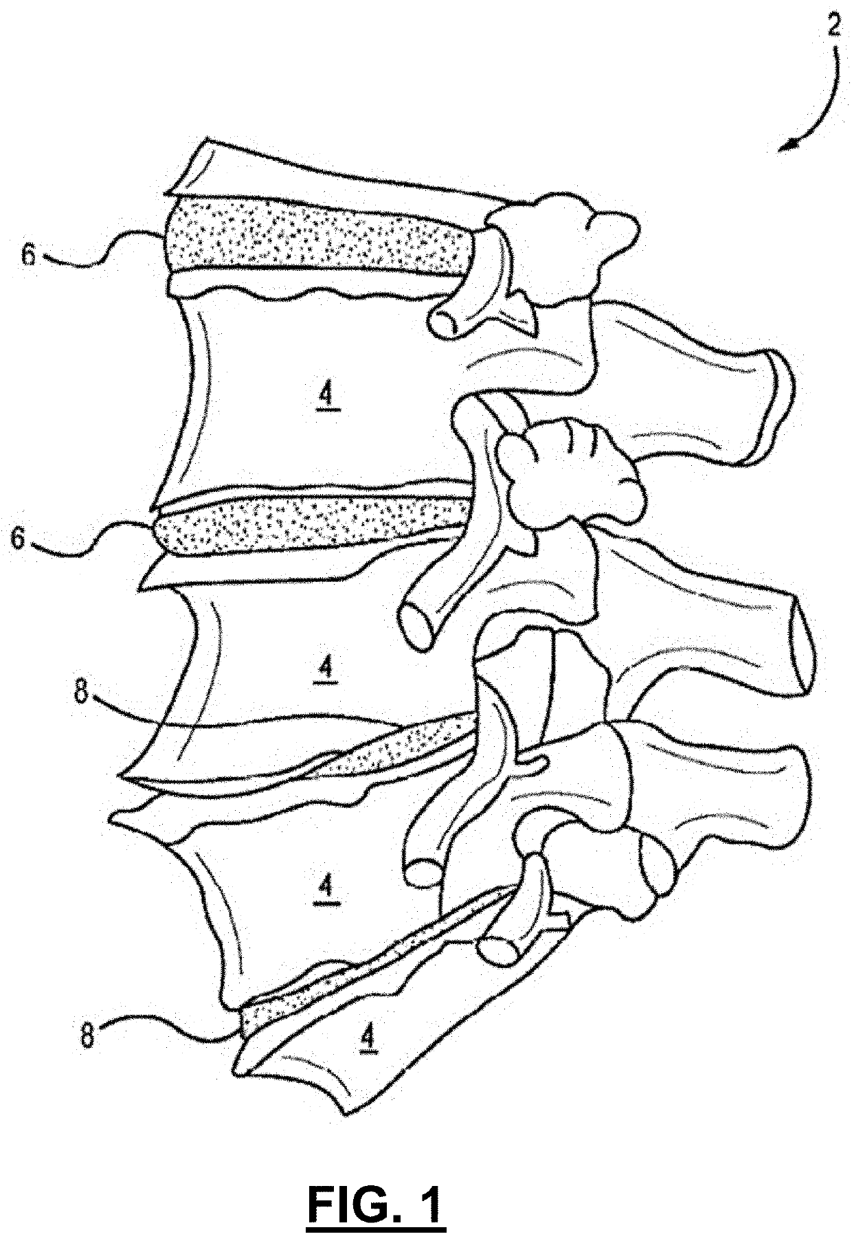
Discs 6 are, however, subject to various injuries and / or disorders which may interfere with a disc's ability to adequately distribute pressure and protect vertebrae 4.
For example, disc herniation, degeneration, and infection of discs 6 may result in insufficient disc thickness and / or support to absorb and / or distribute forces imparted to spinal column 2.
Disc degeneration, for example, may result when the inner gel-like center begins to dehydrate, which may result in a degenerated disc 8 having decreased thickness.
This decreased thickness may limit the ability of degenerated disc 8 to absorb shock which, if left untreated, may result in pain and / or vertebral injury.
While pain medication, physical therapy, and other non-operative conditions may alleviate some symptoms, such interventions may not be sufficient for every patient.
Further, since the spinal column is subject to dynamic forces, often changing with each slight movement of the patient, such screw(s) have a tendency to back out (for example, unscrew) and / or dislodge from the interbody device, thereby limiting interbody device's ability to stabilize adjacent vertebrae, and consequently, promote fusion.
Additionally, if the screw(s) back out and / or dislodge from the interbody device, they may inadvertently contact, damage, and / or irritate surrounding tissue.
However, such materials may impede sagittal and / or coronal visibility, thereby preventing visual confirmation of placement and post-operative fusion.
Furthermore, while all metal titanium interbody devices may be generally good for bone ingrowth, they are radio-opaque and, thus, not good for monitoring bony fusion.

Method used


Image

  • Hybrid spinal cages, systems and methods
  • Hybrid spinal cages, systems and methods
  • Hybrid spinal cages, systems and methods

Examples


Embodiment Construction

[0111]The disclosure and the various features and advantageous details thereof are explained more fully with reference to the non-limiting embodiments and examples that are described and / or illustrated in the accompanying drawings and detailed in the following description. It should be noted that the features illustrated in the drawings are not necessarily drawn to scale, and features of one embodiment may be employed with other embodiments as the skilled artisan would recognize, even if not explicitly stated herein. Descriptions of well-known components and processing techniques may be omitted so as to not unnecessarily obscure the embodiments of the disclosure. The examples used herein are intended merely to facilitate an understanding of ways in which the disclosure may be practiced and to further enable those of skill in the art to practice the embodiments of the disclosure. Accordingly, the examples and embodiments herein should not be construed as limiting the scope of the dis...


PUM


Abstract

An intervertebral cage structure that comprises a shell main body, with the shell main body may be configured to receive and substantially encapsulate a main body. The shell main body may be configured in a clam-shell shape that include a first plate and a second plate that are connected by a bridge portion, wherein the first and second plates may comprise a surface pattern.

Description

CROSS-REFERENCE TO RELATED APPLICATIONS[0001]This application is a continuation-in-part of U.S. patent application Ser. No. 16 / 505,096 entitled “ACIF CAGE, CAGE SYSTEM AND METHOD,” filed Jul. 8, 2019, which is a continuation-in-part of U.S. patent application Ser. No. 15 / 220,090 entitled “ACIF CAGE, CAGE SYSTEM AND METHOD,” filed Jul. 26, 2016, the disclosures of which are each incorporated by reference herein in their entireties.[0002]This application further claims the priority of U.S. Provisional Patent Application 63 / 063,853 entitled “CAGE SYSTEM AND METHODS FOR ENHANCED BONE INTERFACE AND GROWTH,” filed Aug. 10, 2020, the disclosure of which is incorporated by reference herein in its entirety.FIELD OF THE DISCLOSURE[0003]The present disclosure relates generally to medical devices, and more specifically it relates to intervertebral and intradiscal devices, systems, and methods for deployment within a body of a patient.BACKGROUND OF THE DISCLOSURE[0004]In mammals, the spinal (or ...

Claims


Application Information

Patent Timeline
Patent Type & Authority Applications(United States)
IPC IPC(8): A61F2/44A61F2/30
CPCA61F2/447A61F2/442A61F2310/00023A61F2002/3093A61F2/30767A61F2/30771A61F2002/30827A61F2002/30828A61F2002/30831A61F2002/30823A61F2002/30904A61F2/4611A61F2002/30836A61F2002/4629A61F2002/30604A61F2002/3092A61F2002/30593A61F2002/30894A61F2/4455A61F2002/30971A61F2002/30841A61F2002/30387A61F2002/30578A61F2002/30131A61F2002/30331A61F2002/30772A61F2/4465A61F2002/30973A61F2002/30883A61F2002/30014A61F2002/30892
Inventor SUH, JONSUH, SEAN
Owner CTL MEDICAL CORP
Why Eureka
Eureka Blog
Learn More