
CNC machine, workstation and components

Pending Publication Date: 2022-01-27
CHERPURNY MARK
View PDF0 Cites 0 Cited by
  • Summary
  • Abstract
  • Description
  • Claims
  • Application Information

AI Technical Summary

Benefits of technology

The patent text describes a machine that uses wheels for linear motion, but this results in lower precision. The debris from the machine can deflect the wheels, causing them to move in ways that reduce accuracy. If there is enough debris, the wheels can get jammed. The machine also has a leg assembly that can be extended to position the machine up from the floor or folded to make it easier to transport or store. This makes the machine easier to move and helps it to maintain its accuracy.

Problems solved by technology

If that structure has low rigidity, then the displacement or deformation of the structure during operation of the machine will result in reduced precision.
This is one reason, among several, why extruded aluminum elements have high tolerances, with a consequent loss of precision for the CNC machine.
The use of wheels for linear motion also results in lower precision.
Debris from the CNC machine can deflect the wheels as they travel and reduce precision.
If there is enough debris, the wheels can get jammed.

Method used


Image

  • CNC machine, workstation and components
  • CNC machine, workstation and components
  • CNC machine, workstation and components

Examples


Embodiment Construction

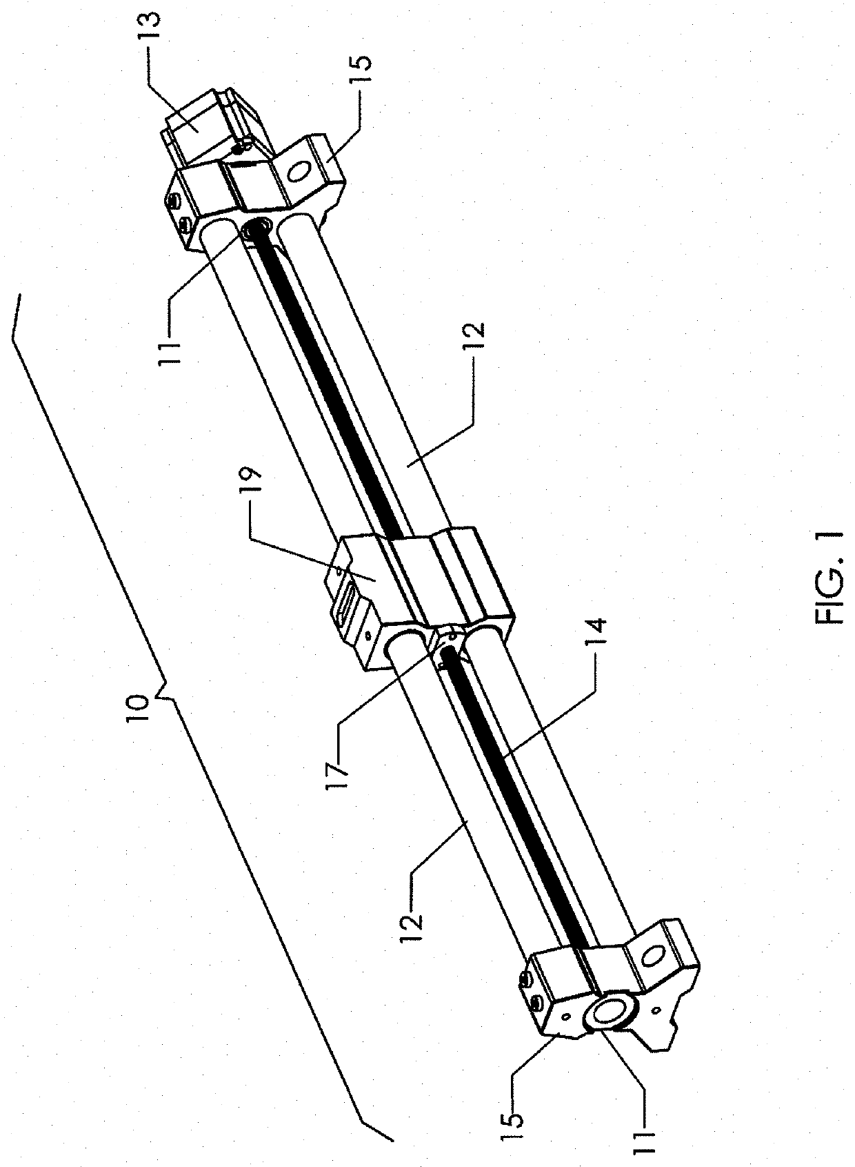
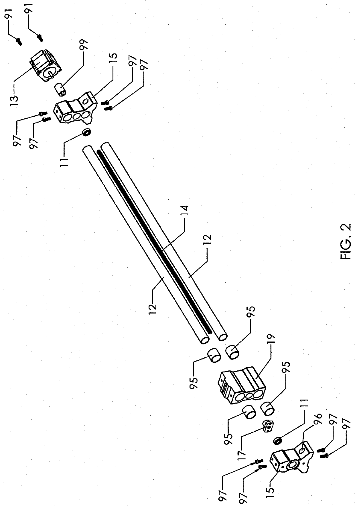
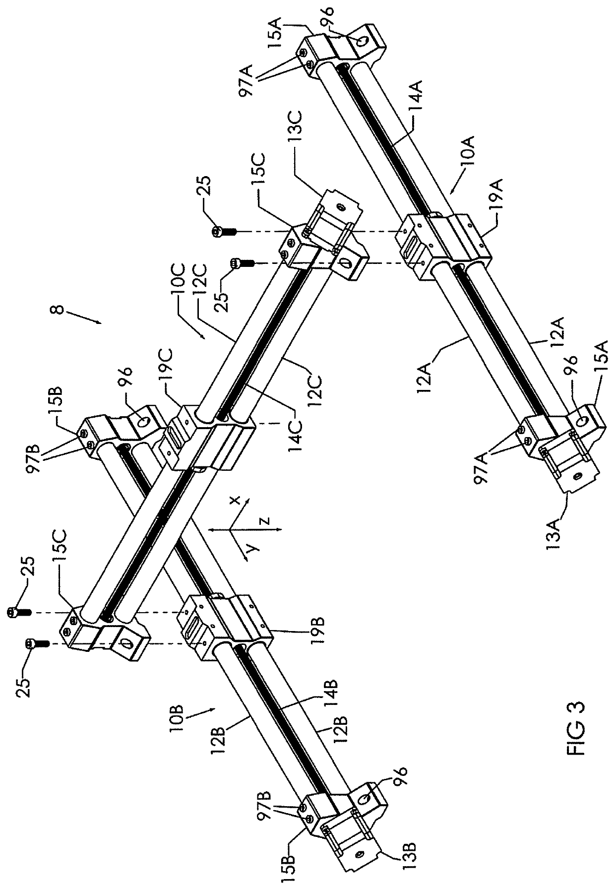
[0070]Referring now to FIGS. 1 and 2, a support frame in the form of linear rail assembly 10 is shown. The linear rail assembly comprises two support frame elements 12. The support frame elements extend between, and are held by, frame ends 15, forming a rigid structure. Preferably, frame elements 12 comprise steel tubing, as described in more detail below. It will be appreciated that the linear rail assembly 10 shown in FIG. 1 is preferably a modular component that can inter alia be used in an X-direction support frame as referred to herein, or in a Y-direction support frame as described herein. Each of these support frames may comprise more than one such rail assembly, though in the preferred embodiment the X-direction support frame includes one such assembly 10 and the Y-direction support frame two.

[0071]The assembly 10 also includes a linear translator, which preferably takes the form of ball screw 14. Mounted on the two frame elements 12 is a traversing element, optionally in th...


PUM


Abstract

A Computer Numerical Control (CNC) machine, including a computer numerical controller, the CNC machine comprising a tool spindle for holding and actuating a tool for contacting a workpiece; a support frame comprising at least one frame element carrying the tool spindle; at least one angle adjustment actuator, coupled to the support frame and the spindle for deflecting an angle of contact of the tool to the workpiece; a motion actuator for causing movement of the tool spindle and tool; an electronic controller for controlling the motion actuator.

Description

RELATED APPLICATIONS[0001]This application is a continuation-in-part of U.S. application Ser. No. 16 / 866,381, filed May 4, 2020, entitled “CNC Machine, Workstation And Components, which claims the benefit of U.S. Provisional Application No. 62 / 842,243, filed May 2, 2019, which are hereby incorporated herein by reference in their entireties.FIELD OF THE INVENTION[0002]This invention relates to the field of CNC (Computer Numerical Control) machines, including related workstations and components thereof.BACKGROUND OF THE INVENTION[0003]There are a variety of cutting machines commonly in use. Among them are lathes, mills, routers and grinders. More recently, such machines have taken the form of CNC (Computer Numerical Control) machines, which are computer controlled for high precision. Such machines typically operate continuously for a substantial period of time, according to how they have been programmed. This is in contrast to a traditional machine being operated by a person, which ma...

Claims


Application Information

Patent Timeline
IPC IPC(8): B23Q1/01B23C1/12B23C1/06
CPCB23Q1/015B23C1/12B23C2260/76B23C2260/04B23C1/06B23C1/20B23Q1/621B23Q9/0014
Inventor CHERPURNY, MARK
Owner CHERPURNY MARK
Learn More