Rod system including at least two rods and connector device for rods
- Summary
- Abstract
- Description
- Claims
- Application Information
AI Technical Summary
Benefits of technology
Problems solved by technology
Method used
Image

Examples
first embodiment
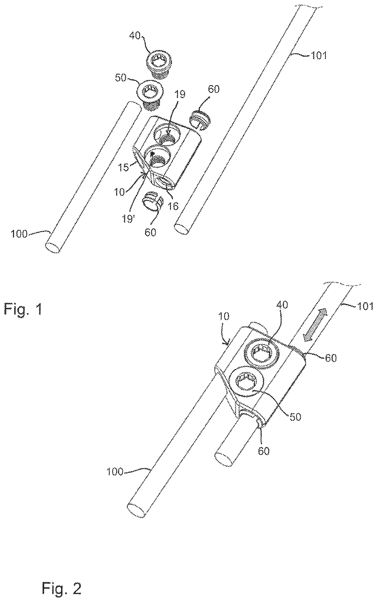
[0070]Referring to FIGS. 1 and 2, a rod system includes a connector including a main body 10 and at least a first rod 100 and a second rod 101 that are intended to be connected by the connector. The rod system further includes at least one, and optionally two fixation members 40, which may be identical. One of the fixation members 40 is configured to fix the first rod 100 to the main body 10. The other one of the fixation members 40 may be used to fix the second rod 101 to the main body, if desired. Further optionally, the rod system may include a closure member 50 that is configured to close an orifice in the main body 10 when the second rod 101 is intended to remain slidable. Sliding members 60 may also be part of the rod system that facilitate sliding of the second rod 101 in the main body 10.
[0071]The first rod 100 and the second rod 101 may be substantially identical. They may have a circular cross-section and preferably a smooth surface. However, the rods are not limited to s...
second embodiment
[0095]In the rod system of the second embodiment, the first rod 100′ is fixed to the main body 10′ in a specific axial position. The fixation is effected by the pin 70 engaging the recess 100a of the first rod 100′. As the pin may be press-fit into the pin hole 27, the axial and rotational fixation of the first rod 100′ is permanent during ordinary use of the rod system. Moreover, the rod 100 can also be welded to the main body 10′, so that the connection is non releasable.
[0096]In use, two fixation members 40 can be placed into the second and third orifice 19′, 119, respectively, so that an enhanced fixation can be achieved by using two fixation members. Alternatively, one fixation member 40 and one closure member 50 may be used or two closure members 50 may be used for the second and third orifices 19′, 119 to keep the second rod 16 slidable. It shall be noted that the orifices 19′, 119 can also remain open, i.e. without inserting a closure member 50.
[0097]In a modified embodiment...
third embodiment
[0099]The rod system has an even more reduced size in the length direction. In a modified embodiment, the first rod 100′ and the main body 10″ can also be a monolithic part, so that the pin is not needed.
[0100]Referring to FIGS. 31 and 32, a still further embodiment of a rod system will be described. The rod system includes a rod 200 which may be identical to the rod 100 or 101 of the previous embodiments, and a connector including a main body 1000 and a fixation member 40. The main body 1000 is a body with a top 11′, a bottom 12′, and sides 13′, 14′, wherein the sides may have a substantially cylindrical outer surface. It shall be noted, however, that the overall shape of the main body can be any shape, for example, cuboid. In the top 11′, a single rod seat 150 is formed which is substantially cylinder segment-shaped for a circular rod 200. The rod seat is open, such that the circular rod can be inserted from the top 11′. Laterally offset from the rod seat 150, an orifice 190 is f...
PUM
 Abstract
Description
Claims
Application Information
 - R&D
- Intellectual Property
- Life Sciences
- Materials
- Tech Scout
- Unparalleled Data Quality
- Higher Quality Content
- 60% Fewer Hallucinations
Browse by: Latest US Patents, China's latest patents, Technical Efficacy Thesaurus, Application Domain, Technology Topic, Popular Technical Reports.
© 2025 PatSnap. All rights reserved.Legal|Privacy policy|Modern Slavery Act Transparency Statement|Sitemap|About US| Contact US: help@patsnap.com