
Apparatus and method for improving at least one physical property of an extruded plastic material

a technology of extrusion and plastic material, applied in the field of apparatus and a method for improving at least one physical property of an extruded plastic material, can solve the problems of high energy loss, special precautions for handling radioactive radiation, etc., and achieve the effect of easy adjustment of intensity and/or the amount of laser light emitted per unit of tim

Inactive Publication Date: 2022-01-20
HANS WEBER MASCHFAB
View PDF1 Cites 0 Cited by
  • Summary
  • Abstract
  • Description
  • Claims
  • Application Information

AI Technical Summary

Benefits of technology

The invention aims to provide an apparatus that can enhance physical properties of plastic materials during extruding in a simple and energy-efficient way. The technical effects of the invention are improved energy introduction into the extruded plastic material and simplified and efficient operation.

Problems solved by technology

The disadvantage of these processes is that handling radioactive radiation requires special precautions and high energy losses occur with infrared radiation and the salt baths, and in the case of salt bath crosslinking the heat input is only via thermal conduction.

Method used


Image

  • Apparatus and method for improving at least one physical property of an extruded plastic material
  • Apparatus and method for improving at least one physical property of an extruded plastic material
  • Apparatus and method for improving at least one physical property of an extruded plastic material

Examples


first embodiment

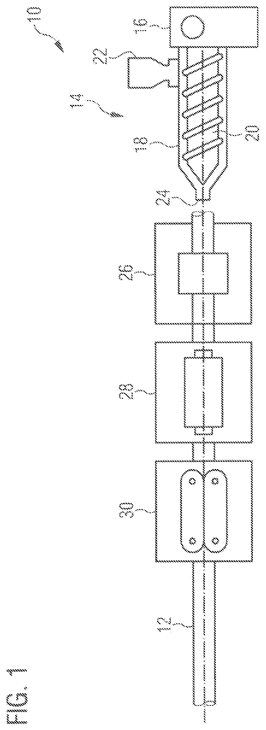
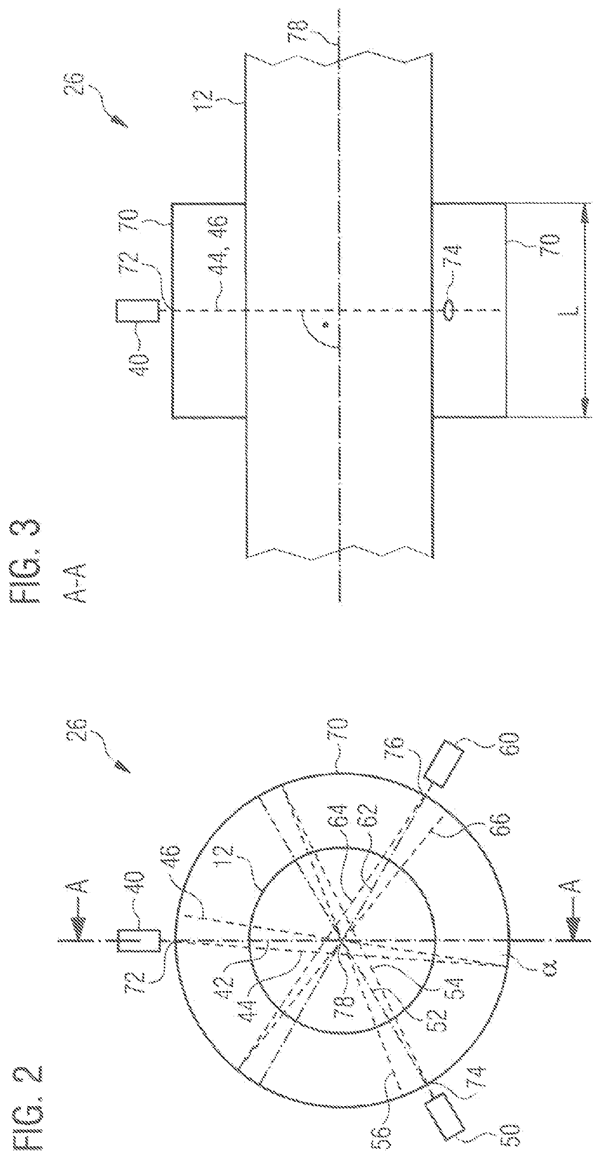
[0040]FIG. 2 shows a schematic representation of the laser unit 26 of the arrangement 10 according to FIG. 1. FIG. 3 shows a sectional view of the laser unit 26 according to FIG. 2 along the cutting line A-A. In the present embodiment, the laser unit 26 has three lasers 40, 50, 60 arranged outside a reflector 70. The center line 78 of the reflector 70 coincides with the longitudinal axis of the extrusion product 12, which is also referred to as extruded plastic material. In other embodiments, the center line 78 of the reflector 70 and the longitudinal axis of the extruded plastic material may be spaced apart and parallel or intersect at an acute angle. In other embodiments, in particular more or fewer lasers 40, 50, 60 may be provided.

[0041]The lasers 40, 50, 60 each emit a laser beam 44, 54, 64 that passes through the extrusion product 12 and strikes and is reflected by the reflector 70 so that a reflected laser beam 46, 56, 66 is reflected such that it again passes through the ext...

second embodiment

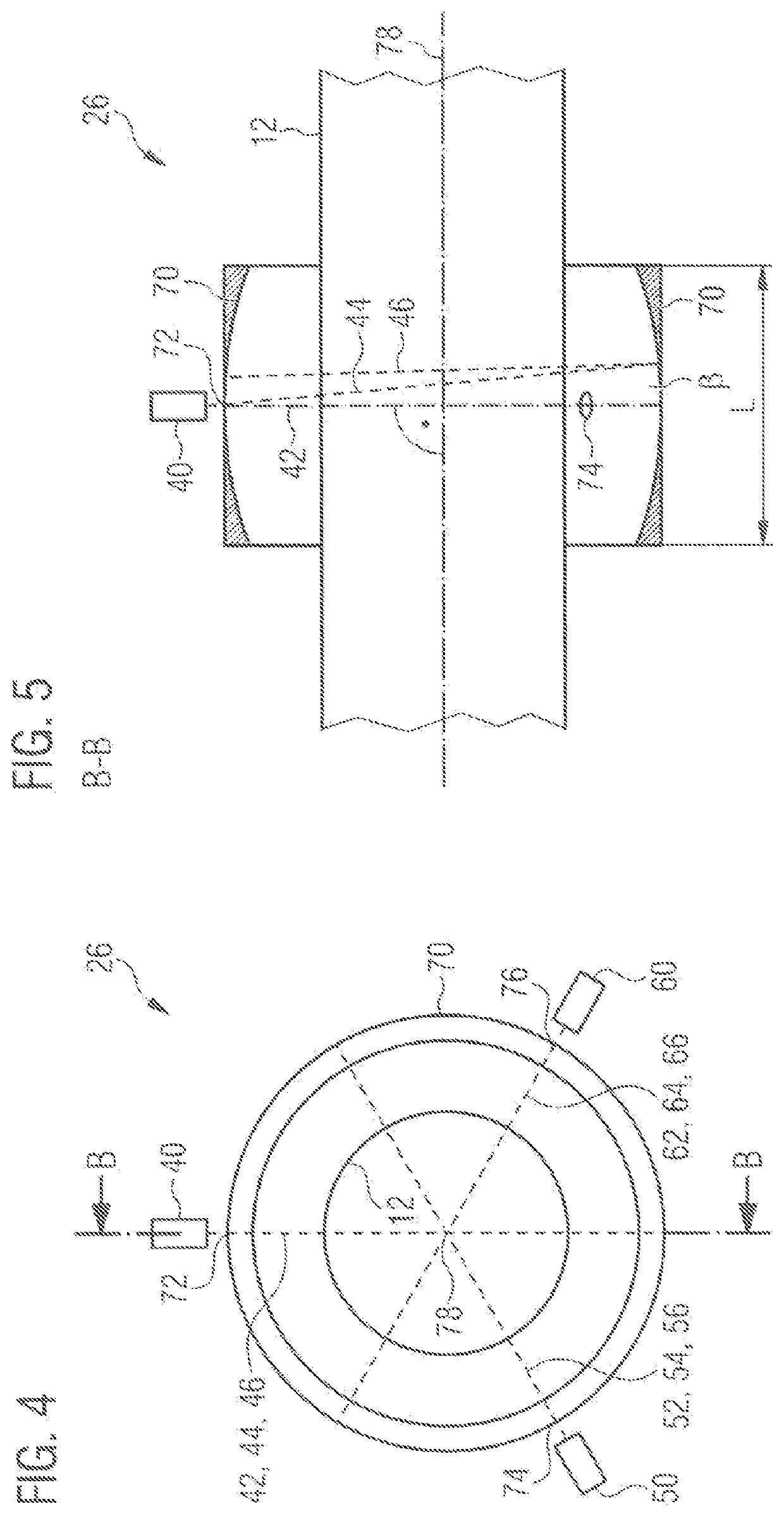
[0043]FIG. 4 shows a schematic representation of the laser unit 26 of the arrangement according to FIG. 1. Elements with the same structure or the same function have the same reference signs. FIG. 5 shows a sectional view of the laser unit 26 according to FIG. 4 along the cutting line B-B.

[0044]In contrast to the first embodiment according to FIGS. 2 and 3, the reflector 70 in the second embodiment has a concavely curved reflective surface. The laser units 40, 50, 60 are oriented to intersect the center line 78 of the reflector 70 and have an angle β of a straight line between the exit point of the laser beam 44 and the center line 78 in a plane orthogonal to the center line 78. The curvature of the concave surface of the reflector 70 is selected such that the reflected laser beams 46, 56, 66, including the multiple reflected laser beams, remain in the region of the reflector 70 and penetrate the extrusion product 12 multiple times, preferably 100 to 10,000 times. Preferably, the ex...


PUM

PropertyMeasurementUnit
angleaaaaaaaaaa
angleaaaaaaaaaa
lengthaaaaaaaaaa

Abstract

An apparatus and a method for improving at least one physical property of an extruded plastic material comprise an extruder for extruding the plastic material as well as a laser unit with at least one laser for irradiating the extruded plastic material with laser light. Further, the apparatus has at least one laser light-reflecting reflector arranged at a distance to the extruded plastic material. The laser and the reflector are arranged and designed such that the laser light emitted by the laser is incident on the reflector through the extruded plastic material, the reflector reflects the incident laser light such that at least a part of the reflected laser light hits the extruded plastic material.

Description

CROSS-REFERENCE TO RELATED APPLICATIONS[0001]This application claims priority to Germany application DE 10 2020 118 667.3, filed Jul. 15, 2020.TECHNICAL FIELD[0002]The invention relates to an apparatus and a method for improving at least one physical property of an extruded plastic material. Such an extruded plastic material is, in particular, a polyolefin that is crosslinkable by the supply of energy. The apparatus comprises an extruder for extruding the plastic material.BACKGROUND[0003]Extruded polyolefins, such as polyethylene (PE), are crosslinked in the manufacturing process after extrusion to improve their physical properties. Such crosslinking can, in particular, improve the temperature resistance of the extruded polyolefins. In particular, one or more peroxides can be used as crosslinking agents in the polyethylene, which trigger the crosslinking process by increasing the temperature through the supply of energy, especially thermal energy. In particular, radioactive radiatio...

Claims


Application Information

Patent Timeline
Patent Type & Authority Applications(United States)
IPC IPC(8): B29C48/91B29C48/06B29C48/88B29C48/00
CPCB29C48/91B29C48/06B29K2105/0032B29C48/022B29C48/911B29C35/0277B29C35/10B29C2035/0838B29K2023/0691B29C48/09B29C2791/009B29K2105/24
Inventor WEBER, JOHANNES
Owner HANS WEBER MASCHFAB
Learn More