Fastener placement tool

Active Publication Date: 2022-01-13
AVDEL UK LTD
View PDF2 Cites 0 Cited by
  • Summary
  • Abstract
  • Description
  • Claims
  • Application Information

AI Technical Summary

Benefits of technology

The invention is a tool used for placing fasteners that has been designed to overcome its previous limitations. The tool uses an electro-mechanical system instead of a hydro-pneumatic system to control its operation, making it easier for operators to use. The use of electro-mechanical drives also reduces the time the tool needs to be serviced. In simple terms, this tool is designed to be more flexible and efficient.

Problems solved by technology

This operation, particularly when occurring as a sequential rapid-placement one, results in wear of the mandrel, the mandrel head and the tool jaws which control operation of the mandrel.
This ultimately necessitates replacement of the worn tool parts over time.
With the known placement tools employing hydraulic and pneumatic control systems, replacement of worn tools parts, particularly the jaws used to grasp and control the mandrel, is a lengthy process, often requiring at least partial disassembly of the whole tool.
Particular care needs to be taken with such disassembly, as damage to either the hydraulic or the pneumatic systems could be costly to repair.

Method used


Image

  • Fastener placement tool
  • Fastener placement tool
  • Fastener placement tool

Examples


Embodiment Construction

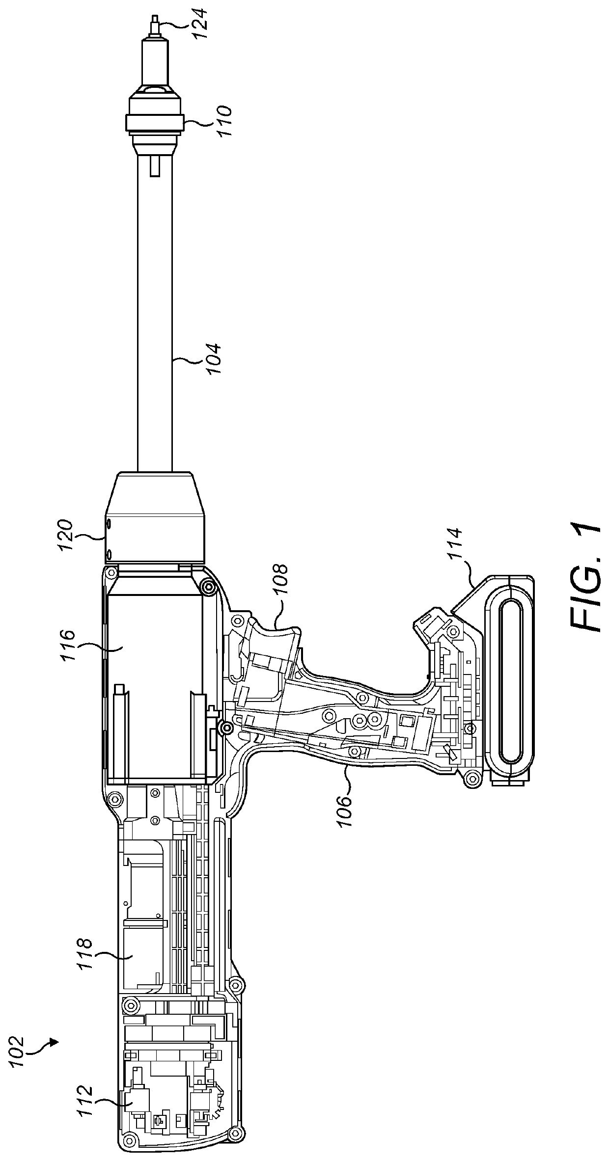
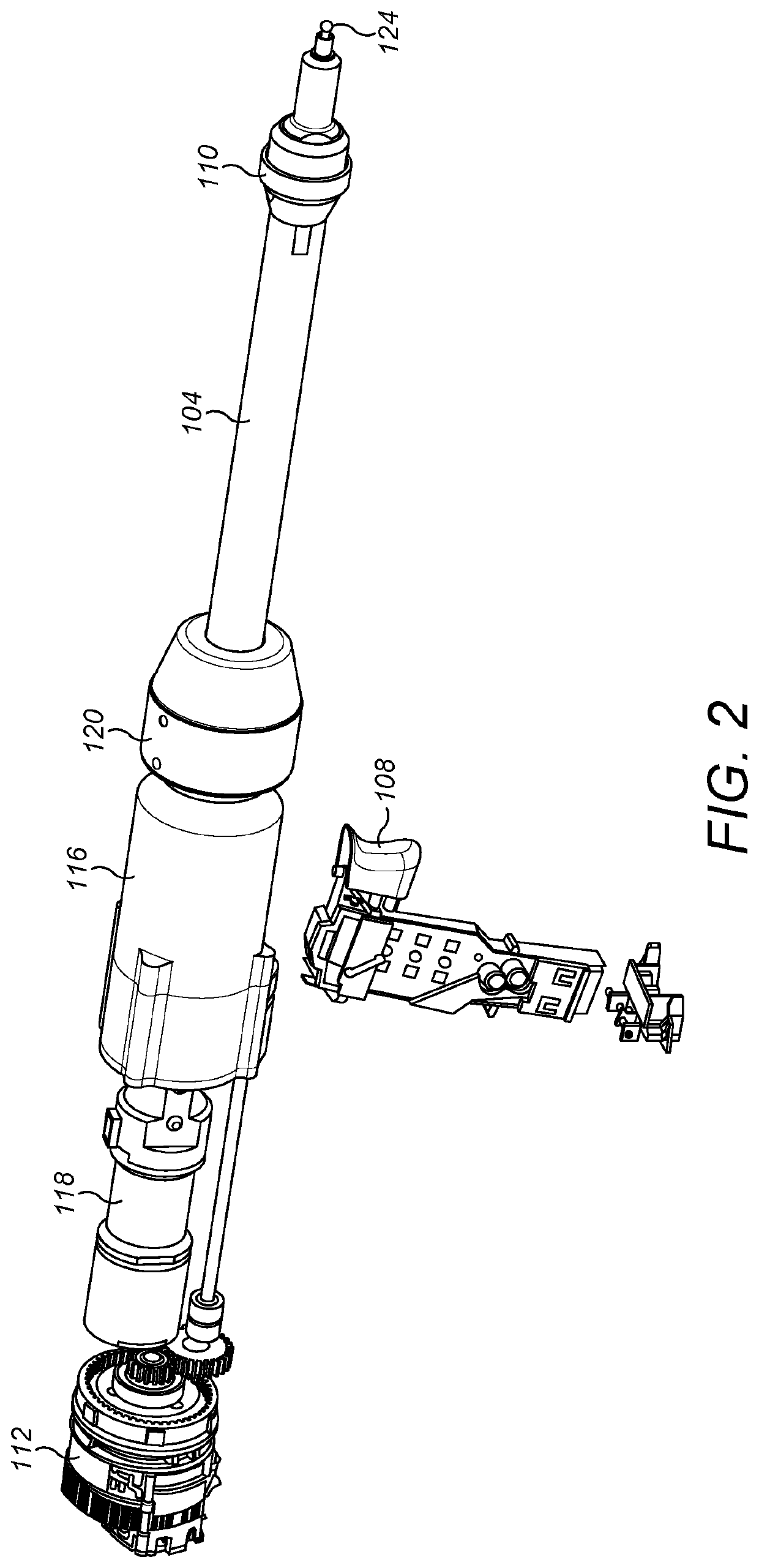
[0034]Referring firstly to FIGS. 1 and 2, the fastener insertion tool 102 in accordance with the present invention comprises a barrel 104, formed as an axially-extending hollow metallic cylinder, in this example, aluminium, having a distal and a proximal end. In FIG. 1, the distal end is to the right of the figure and the proximal end is to the left. The tool 102 includes a user-graspable handle 106 which has formed thereon an actuation trigger 108. This means that the proximal end of the barrel 104 is adjacent the tool handle 106.

[0035]The distal end of the barrel 104 has formed thereon a nose jaw assembly 110, which will be described in detail below. The purpose of the nose jaw assembly is to form the contact point between the tool 102 and the workpieces to which fasteners are to be applied and to locate the fasteners during their placement operation, as will be explained below.

[0036]The fasteners with which the tool 102 operates are so-called blind fasteners, in this example rive...


PUM


Abstract

A fastener placement tool has a mandrel able to place a series of captive rivets in sequence. The tool employs a single electric motor capable of driving the tool into either a first cycle for rivet placement, to a second cycle for selective release of the mandrel form the tool for rivet replenishment. The tool includes a user-operable switch actual to select which of the first or second cycle the tool is to operate.

Description

CROSS-REFERENCE TO RELATED APPLICATIONS[0001]This application is a continuation of PCT Application No. PCT / EP2020 / 060763, filed on Apr. 16, 2020 which claims priority from British Application No. 1907290.9, filed on May 23, 2019, the entire disclosure of which is incorporated herein by reference.BACKGROUND OF THE PRESENT INVENTION[0002]The present invention relates generally to a fastener placement tool and has particular, although not exclusive, relevance to such tools as are used to place blind-side rivets.[0003]Fastener placement tools are well known and those used for placement of so-called blind-side rivets are often used to repeatedly place rivets of a specified length and diameter. Such repeated placement may occur, for example, in manufacturing environments, such as assembly lines, or the like.[0004]Where repeated placement of rivets (or other types of fastener) occurs, there may also be the need for such repeated placement to be as rapid as possible, in order to enhance the...

Claims


Application Information

Patent Timeline
IPC IPC(8): B21J15/34B21J15/10B21J15/26B21J15/28
CPCB21J15/34B21J15/105B21J15/043B21J15/28B21J15/26
Inventor CUMERSDALE, TIMSEEWRAJ, ANGUS
Owner AVDEL UK LTD
Why Eureka
Try Eureka