
Method for assessing the operatability of a sensor for detecting soot

a sensor and operation method technology, applied in the field of methods and apparatus for detecting soot particles, can solve the problems of short time-consuming and laborious, high current results, and inaccuracy of measurement, and achieve the effect of increasing the reliability of the evaluation of the functionality of the sensor

Pending Publication Date: 2022-01-06
ROBERT BOSCH GMBH
View PDF3 Cites 1 Cited by
  • Summary
  • Abstract
  • Description
  • Claims
  • Application Information

AI Technical Summary

Benefits of technology

The present invention provides a method for measuring the electrical resistance between two measurement electrodes in a sensor. The resistance heating element is deactivated after burn-off of soot, and accurate measurements are made after a delay. A second variable is measured to evaluate the sensor's functionality, which improves accuracy and reliability. The method also includes applying a voltage between the measurement electrodes during the activation, maintenance, and deactivation of the resistance heating element and measuring the resulting electrical resistance to compensate for transient effects. These refinements increase the reliability of the sensor measurement process.

Problems solved by technology

It has also been recognized, in particular, that switching-on and shut-off operations of the resistance heating element, which are associated, for example, with regulation of the sensor temperature to a constant temperature, result in disruptions to the measured current.
The inventors have furthermore recognized that transient effects can occur in the context of measurement of the first variable representing the electrical resistance between the measurement electrodes, and can in turn result in measurement inaccuracies.
It has been observed, for example, that directly after the measurement voltage between the measurement electrodes is applied or increased, particularly high currents result for a short time due to the movement of ions in the sensor.

Method used


Image

  • Method for assessing the operatability of a sensor for detecting soot
  • Method for assessing the operatability of a sensor for detecting soot
  • Method for assessing the operatability of a sensor for detecting soot

Examples


Embodiment Construction

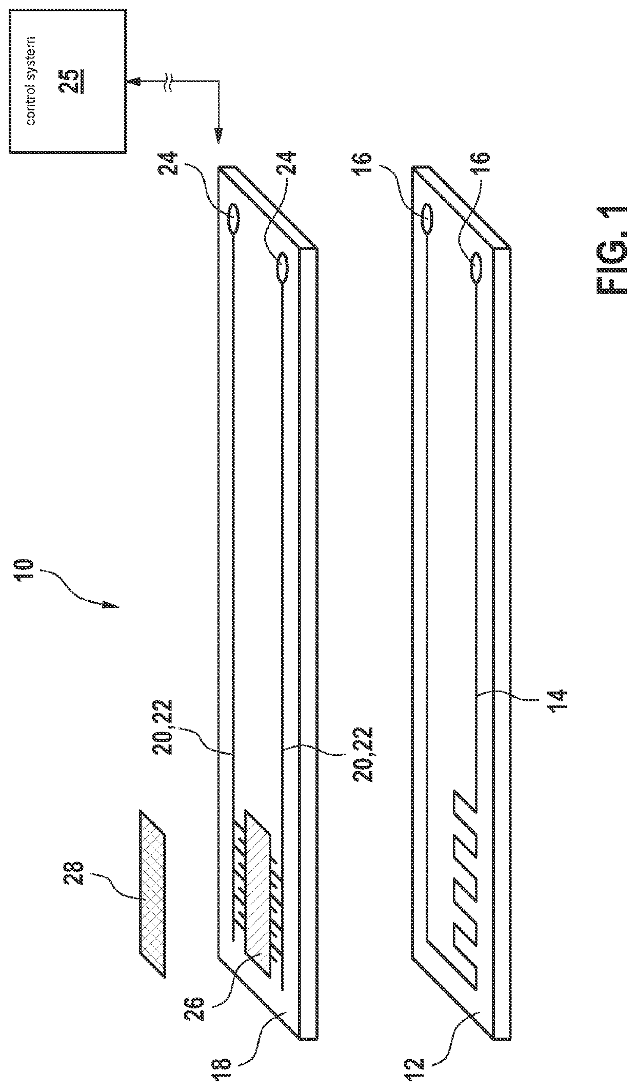
[0019]FIG. 1 shows a sensor 10 for detecting soot in a gas flow, for example in an exhaust gas flow of an internal combustion engine, which serves for installation in an exhaust system of a motor vehicle. Sensor 10 is disposed, for example, downstream from a soot filter of a motor vehicle having a diesel internal combustion engine.

[0020]Sensor 10 encompasses a plate-shaped carrier layer 12 that is produced at least in part from an electrically insulating material, for example from a ceramic such as aluminum oxide. Integrated into carrier layer 12 is a resistance heating element 14 that is connectable via contacts 16 to a suitable voltage source and serves to burn off from sensor 10 particles, such as soot particles, that may have been deposited.

[0021]Arranged on carrier layer 12 is a plate-shaped substrate 18 that is produced at least in part from an electrically insulating material, for example a ceramic such as aluminum oxide. A structure made up of two measurement electrodes 20 i...


PUM


Abstract

A method for evaluating the functionality of a ceramic sensor for detecting soot, the sensor including two measurement electrodes exposable to an exhaust and spaced apart from one another, and an electrical resistance heating element. The method includes: activating the resistance heating element to heat up the sensor and to burn soot off the two measurement electrodes; then deactivating the resistance heating element; then waiting for a first predetermined time period and / or waiting until a signal that is received from the sensor and represents the sensor temperature reaches a first predefined value; then measuring a first variable representing the electrical resistance between the measurement electrodes; then evaluating the functionality of the sensor based on the first variable representing the electrical resistance between the measurement electrodes.

Description

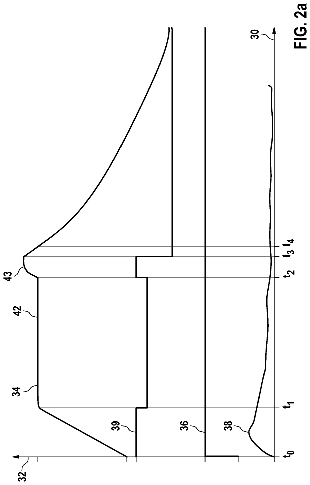
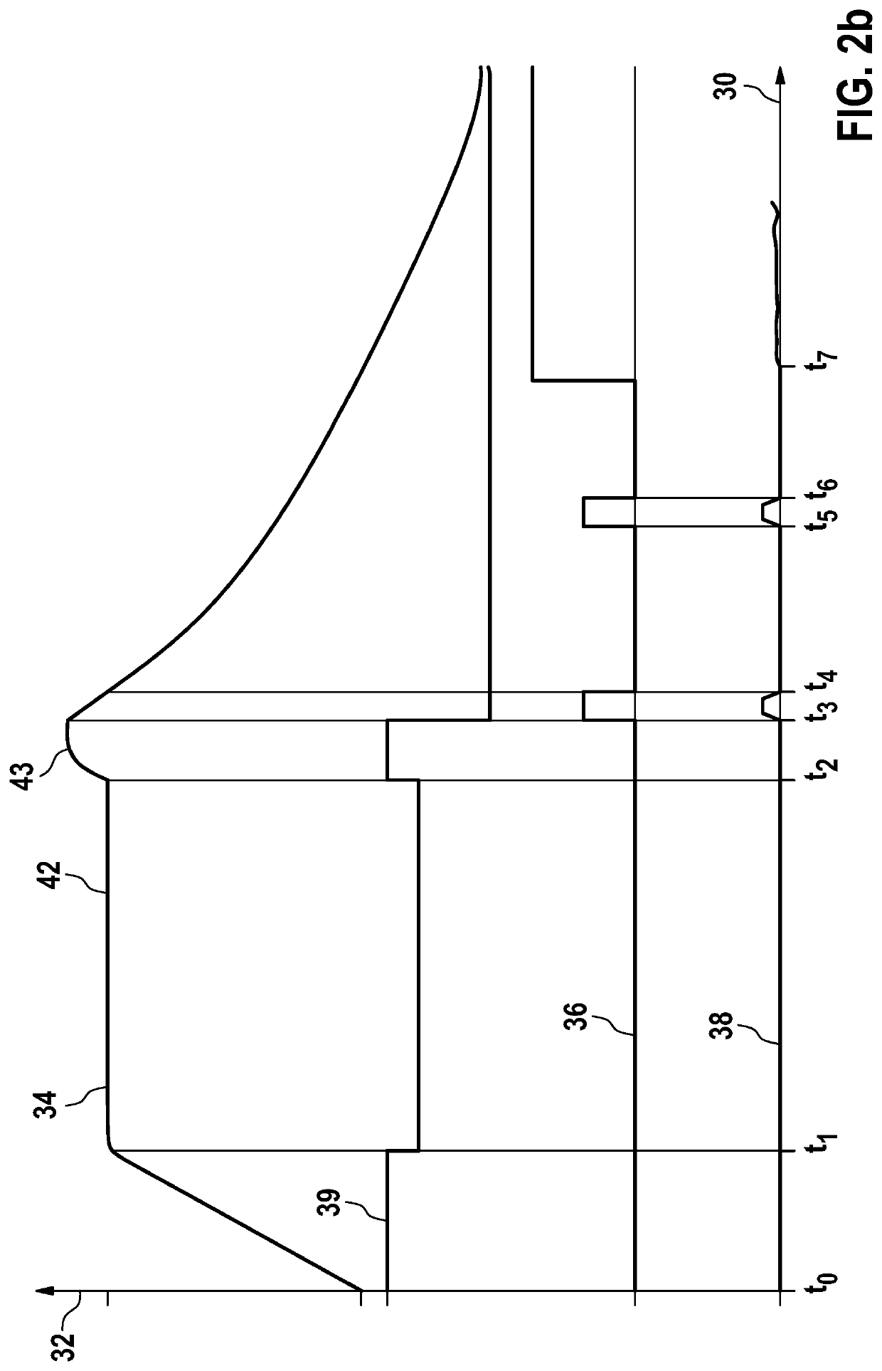
BACKGROUND INFORMATION[0001]German Patent Application No. DE 10 2012 210 525 A1 describes a method and an apparatus for detecting soot particles in the exhaust gas of internal combustion engines.[0002]Ceramic resistive soot sensors, having two measurement electrodes exposable to an exhaust gas and a resistance heating element, are conventional. Measurement of a soot concentration in the exhaust gas is based on deposition of the soot particles between the measurement electrodes and a consequently reduced electrical resistance between the measurement electrodes. The soot particles can be burned off using the resistance heating element, so that a new measurement can be started.[0003]It is also conventional to monitor the integrity of the electrodes, and thus the functionality of the sensor, by the fact that after a regeneration, i.e., when a conductive connection due to soot is ruled out, the temperature of the sensor is held constant with a resistance heating element and at the same t...

Claims


Application Information

Patent Timeline
IPC IPC(8): G01N27/04
CPCG01N27/045G01N27/043G01N33/0006G01N15/0656G01N15/0606G01N33/007
Inventor HERWEG, KAROLASCHILLING, CAROLIN MARIAKLENK, MATHIAS
Owner ROBERT BOSCH GMBH
Learn More