Aircraft control for endurance and fuel economy

a fuel economy and endurance technology, applied in the field of endurance and aircraft control, can solve the problems of difficult and impractical performing such an aerodynamic analysis, calculation subject to weight measurement errors, etc., and achieve the effect of improving the airspeed and efficient aircraft operating poin

Pending Publication Date: 2021-12-30
INNOVATIVE SOLUTIONS & SUPPORT
View PDF3 Cites 4 Cited by
  • Summary
  • Abstract
  • Description
  • Claims
  • Application Information

AI Technical Summary

Benefits of technology

[0011]Optionally, the system and method may include further comparing the rates of energy consumption at the prior airspeed and the increased airspeed, and in response to the rate of energy consumption at the increased airspeed being lower than at the prior airspeed, increasing the engine power such that the aircraft incrementally speeds up from a prior airspeed to an increased airspeed by a third increment, where this increased airspeed corresponds to a more efficient operating point of the aircraft than any prior airspeed.

Problems solved by technology

In practice, performing such an aerodynamic analysis is difficult and impractical.
For instance, the calculation is subject to weight measurement errors, variations in engine performance and modifications to the aircraft fuselage and the rigging of the aircraft.

Method used


Image

  • Aircraft control for endurance and fuel economy
  • Aircraft control for endurance and fuel economy
  • Aircraft control for endurance and fuel economy

Examples


Embodiment Construction

[0025]It should be noted that aspects of this disclosure are applicable in any powered aircraft, including traditional fuel-burning aircraft (propeller-driven, turboprop, jet, or other), electric aircraft (battery-, solar-, or fuel cell-powered), or hybrid-powered aircraft. In the following description, various embodiments are described in the context of one, or some, types of propulsion or propulsion-energy-delivery systems; however, it should be understood that principles of the described embodiments may be suitably applied to other types of aircraft having other propulsion or propulsion-energy-delivery systems with suitable adaptation which is within the skill of aircraft technologists.

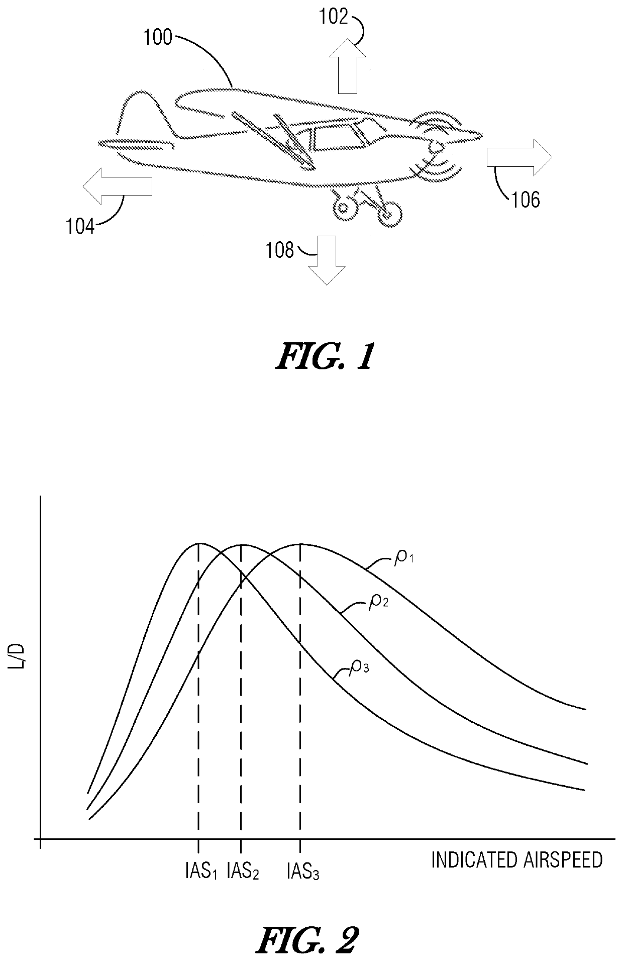
[0026]FIG. 1 is a simplified diagram illustrating aircraft 100 and basic forces involved in its flight. Aircraft 100 generates lift 102 from its forward motion by directing air downward using primarily the shape and orientation of the body of aircraft 100 (e.g., its wings, fuselage, and control sur...


PUM


Abstract

An autothrottle of an aircraft is configured to reduce engine power of the aircraft such that the aircraft incrementally slows from a prior airspeed to a reduced airspeed by a first increment, and compare the rates of energy consumption at the prior airspeed and the reduced airspeed. In response to the rate of energy consumption at the reduced airspeed being lower than at the prior airspeed as determined the above operations are repeated. In response to the rate of energy consumption at the reduced airspeed not being less than at the prior airspeed, the autothrottle increases the engine power such that the aircraft incrementally speeds up from a prior airspeed to an increased airspeed by a second increment, the increased airspeed corresponding to a more efficient operating point of the aircraft than any prior airspeed.

Description

PRIOR APPLICATION[0001]This application claims the benefit of U.S. Provisional Application No. 63 / 044,801, filed Jun. 26, 2020, and entitled “METHOD OF OPERATING AN AIRCRAFT TO ACHIEVE A MINIMUM FUEL BURN FOR MAXIMUM FLIGHT ENDURANCE,” the disclosure of which is incorporated by reference herein.TECHNICAL FIELD[0002]The invention relates generally to aeronautics and aircraft control and, more particularly, to throttle control for maintaining efficient flight characteristics.BACKGROUND[0003]The maximum endurance or fuel efficiency for an aircraft depends on a number of factors, including the size and shape of the aircraft, the density of the air, and the flight speed. For a given aircraft, maximum flight endurance is achieved when the aircraft is flown at the most aerodynamically efficient condition. This condition is achieved when the ratio L / D, that is, the ratio of the lift L generated by the aircraft, to the drag D experienced by the aircraft, is maximized. If the airspeed can be ...

Claims


Application Information

Patent Timeline
Patent Type & Authority Applications(United States)
IPC IPC(8): B64D31/06
CPCB64D31/06
Inventor HEDRICK, GEOFFREY S. M.
Owner INNOVATIVE SOLUTIONS & SUPPORT
Why Eureka
Try Eureka