Electric field sensor

a technology of electric field and sensor, which is applied in the direction of power measurement by thermal methods, measurement devices, instruments, etc., can solve the problem of large temperature difference between the first and second temperature sensors

Active Publication Date: 2021-12-23
MBDA UK
View PDF4 Cites 2 Cited by
  • Summary
  • Abstract
  • Description
  • Claims
  • Application Information

AI Technical Summary

Benefits of technology

[0004]Such a device enables electric fields to be measured without any significant perturbation of the electric field to be measured. Such a device can be made to be relatively small compared to an antenna and can therefore map an electric field more accurately than has previously been possible. Moreover the use of the thermal insulator enables the sensitivity of the device to be enhanced, since the thermal insulation retains the heat signal within the absorber. This results in a larger temperature difference between the first and second temperature sensors.
[0014]The thermal insulation may enclose the absorber. Enclosing the absorber mitigates the possibility that air currents may, for example through convection, affect the temperature of the absorber and therefore affect the measurement of electric field.

Problems solved by technology

This results in a larger temperature difference between the first and second temperature sensors.

Method used


Image

  • Electric field sensor
  • Electric field sensor
  • Electric field sensor

Examples


Embodiment Construction

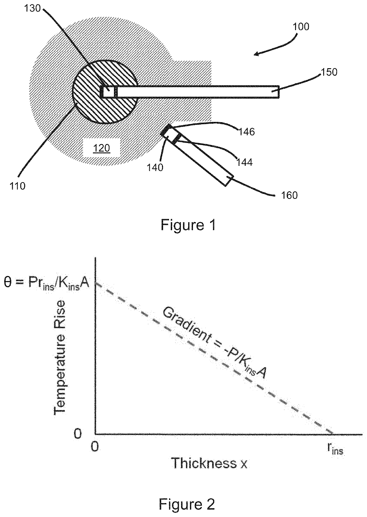
[0028]A device 100 according to a first embodiment of the present invention is shown in cross section in FIG. 1 and is arranged to determine the strength of an ambient radio frequency (RF) electric field. Device 100 comprises a radio frequency absorber material 110 surrounded by thermal insulation 120. The thermal insulation is selected to be transparent to RF radiation. Embedded in the absorber 110 is a first temperature sensor 130. A second temperature sensor 140 is located outside the thermal insulation 120. Both the first and second temperature sensors comprise a material whose optical response varies with temperature. Accordingly the first and second temperature sensors allow the temperatures to be determined by analysing their response to an input optical pulse. In the present example the sensors can be interrogated by transmission of an optical pulse from a control unit. The control unit is connected to the first and second temperature sensors by optical fibres 150 and 160 re...


PUM


Abstract

There is disclosed a device for determining a strength of an oscillating electric field. The device comprises an absorber to absorb radiation at the frequency of the oscillating electric field, and a thermal insulator transparent to radiation at the frequency of the oscillating electric field, which thermal insulator is arranged to thermally insulate the absorber. The device also comprises a first temperature sensor arranged to measure the temperature of the absorber, and a second temperature sensor arranged to measure the temperature external to the thermal insulator. Methods of measuring electric field using such a device, and methods of calibrating such a device, are also disclosed.

Description

FIELD OF THE INVENTION[0001]This invention relates to a sensor for determining the strength of an electric field. More particularly, though not exclusively, the present invention relates to a sensor for determining the strength of a radio-frequency electric field through its heating effect on an absorber material.BACKGROUND[0002]Antennas can be used to measure electric field strength but suffer from a number of disadvantages that prevent their use for certain applications. In particular antennas can be physically too large to make measurements either in confined spaces or to make measurements at a well-defined location. This problem arises because, as antennas are made smaller, the signal picked up by the antenna cables and circuits can grow to become larger than the signal picked up by the antenna. To mitigate this problem, and to ensure sensitivity to small signals is maintained, the antenna requires a larger electromagnetic cross section (and correspondingly a larger physical siz...

Claims


Application Information

Patent Timeline
Patent Type & Authority Applications(United States)
IPC IPC(8): G01R29/08G01R35/00
CPCG01R29/0878G01R35/005G01R29/08G01R35/00G01R21/02
Inventor CHUGG, ANDREW MICHAEL
Owner MBDA UK
Why Eureka
Try Eureka