
Door handle device for vehicle

a technology for sliding parts and handles, applied in the field of door handle devices, can solve the problems of degrading operation feeling, unsmooth feeling for operators, and friction force acting on sliding parts, and achieve the effect of simple structur

Active Publication Date: 2021-12-23
MINEBEA ACCESSSOLUTIONS INC
View PDF10 Cites 1 Cited by
  • Summary
  • Abstract
  • Description
  • Claims
  • Application Information

AI Technical Summary

Benefits of technology

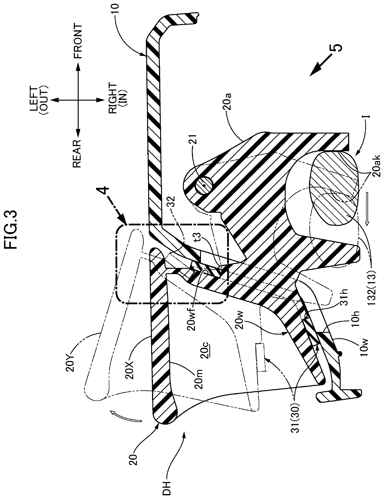
The present invention provides a door handle device for a vehicle that has a simple structure. The device includes an elastic stopper with a main body and a lip part. The main body is attached to either the case member or the handle member and can alleviate impact by making contact with the other member when the handle member reaches the closed position. The lip part is formed to protrude further and elastically urge the receiving surface and the handle member in a direction of separating them from each other when the handle member starts the open-swing from the closed position. This prevents friction force between the parts, improves the operation feeling of the handle member. Additionally, the receiving surface may have a specified part that displaces relative to the handle member during the open-swing, and the lip part can still elastically separate the receiving surface and the handle member to restrain the friction force. The handle member also includes an arm part that is pivotally connected to the case member and the lip part is formed on the stopper main body to surround the openings, preventing wind or water noise and protecting the interior of the case member.

Problems solved by technology

Therefore, due to this sliding, a friction force acts to no small extent so as to give unsmooth feeling to an operator, thereby causing a possibility of degrading operation feeling.
However, even in such a structure, there is a case wherein when open-swing of the handle member is started from the closed position, depending on a direction of the swinging displacement and a direction of an elastic stopper (8), the elastic stopper and the handle member are rubbed against each other to some extent to be in sliding contact with each other, and therefore, a friction force acting on the sliding part may give unsmooth feeling to the operator.

Method used


Image

  • Door handle device for vehicle
  • Door handle device for vehicle
  • Door handle device for vehicle

Examples


Embodiment Construction

[0021]An embodiment of the present invention is explained below by reference to the attached drawings.

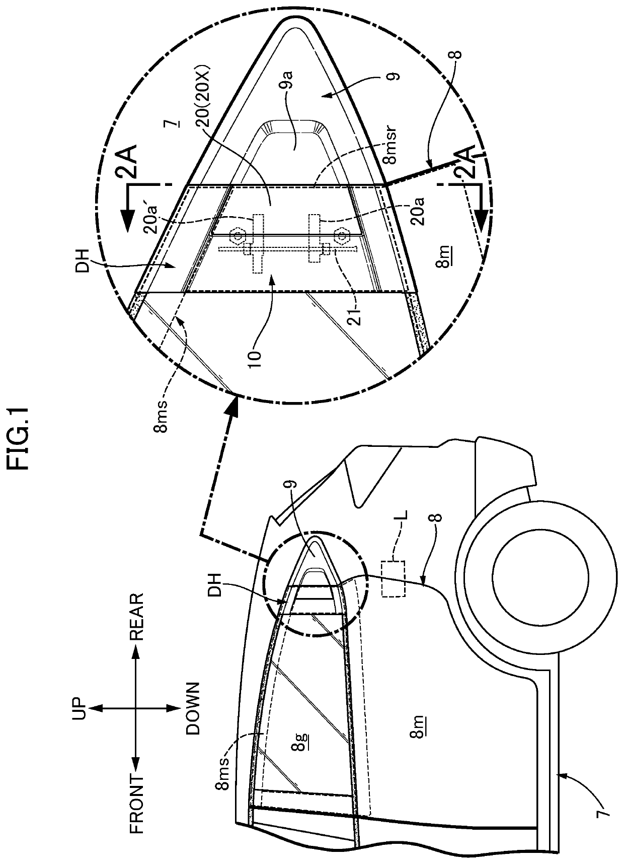
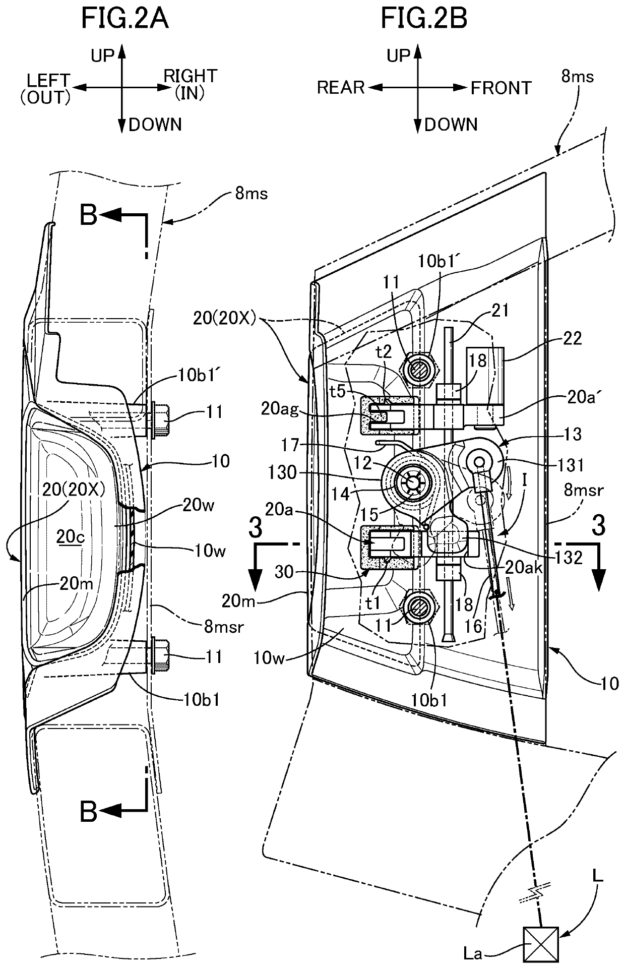
[0022]First, in FIG. 1, front and rear doors are openably and closably mounted on a vehicle body 7 of an automobile as a vehicle so as to respectively close left and right openings of the vehicle body 7. For example, in each of the left and right rear doors 8, a front end part of a door main body 8m is hinge-connected to the vehicle body 7, and a rear end part of the door main body 8m is engageably and disengageably locked to the vehicle body 7 by a door lock mechanism L provided between the rear end part and the vehicle body 7. It is noted that the door lock mechanism L includes a striker not illustrated, which is fixed to the vehicle body side, and a latch La (schematically illustrated in FIG. 2B) on the door side, the latch La being engageable with and disengageable from the striker, an engagement and disengagement structure between the striker and the latch La is conventionally ...


PUM


Abstract

In a door handle device for a vehicle, an elastic stopper includes: a stopper main body having a receiving surface that can be brought into contact with and separated from one of case and handle members, and being attached to the other member; and a lip part formed integrally with the stopper main body. The stopper main body is formed into a shape capable of alleviating impact by bringing the receiving surface into contact with the one member when the handle member swinging in a closing direction reaches a closed position. The lip part is formed to protrude further toward the one member side than the receiving surface in a free state of the lip part, and can exert a resilient force in a direction where the receiving surface and the one member are separated from each other when the handle member starts open-swing thereof from the closed position.

Description

CROSS REFERENCE TO RELATED APPLICATIONS[0001]The present application claims priority under 35 U.S.C. § 119 to Japanese Patent Application No. 2020-108217 filed Jun. 23, 2020 the entire contents of which are hereby incorporated by reference.BACKGROUND OF THE INVENTIONField of the Invention[0002]The present invention relates to a door handle device, particularly, a door handle device for a vehicle, comprising a case member that is to be fixed to a door main body, a handle member that is pivotally supported on the case member so as to be capable of swinging between a predetermined closed position and a predetermined open position, and an urging device that urges the handle member toward the closed position.Description of the Related Art[0003]For example, Japanese Patent Application Laid-open No. 2002-188329 discloses an arrangement of the above-mentioned door handle device for a vehicle, in which an elastic stopper capable of holding the handle member at the closed position against the...

Claims


Application Information

Patent Timeline
Patent Type & Authority Applications(United States)
IPC IPC(8): E05B77/38E05B85/18
CPCE05B77/38E05B85/18E05B85/10E05B79/06E05B85/103E05B77/34
Inventor YAMAGUCHI, YUKISAITOU, YASUHIRO
Owner MINEBEA ACCESSSOLUTIONS INC
Learn More