
Air-Fuel Metering for Internal Combustion Reciprocating Engines

a reciprocating engine and air-fuel technology, applied in the direction of combustion engines, electric control, speed sensing governors, etc., can solve the problems of waste heat that creates no engine power, slow combustion, or incomplete, or both, and reduce power output. or the effect of excess pollution

Pending Publication Date: 2021-12-16
SETAYSHA TECHNICAL SOLUTIONS LLC
View PDF16 Cites 0 Cited by
  • Summary
  • Abstract
  • Description
  • Claims
  • Application Information

AI Technical Summary

Benefits of technology

The system provides reliable fuel delivery over a wide range of operating conditions, is simpler and less expensive than existing EFI systems, and more reliable than carburetors, with reduced mechanical complexity and lower costs, while maintaining accurate air-fuel ratio control.

Problems solved by technology

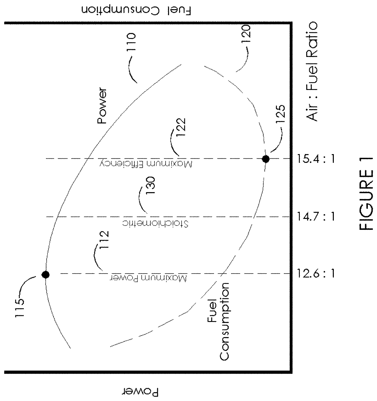
If the combustion mixture consists of too great a proportion of fuel relative to oxygen (also referred to as an “excess” or “rich” AFR or mixture), the combustion will be slow and / or incomplete, resulting in reduced power output, excess pollution, or both.
The excess fuel does not fully combust inside the chamber, resulting in continued burning of the fuel in the exhaust process, resulting in waste heat that creates no engine power as well as increased emissions of unwanted solids (soot) and organic compounds.
An excess of oxygen or air (also referred to as a “deficit” or a “lean” AFR or mixture) results in reduced power output.
With an extreme deficit of fuel in the mixture, the ICE will no longer support combustion and will cease to run.
However, as fuel deficits continue beyond the maximum efficiency point (i.e., as the AFR continues to increase), before the ICE ceases to run altogether it suffers negative effects of increased nitrogen-oxide pollutant emissions and poor running characteristics such as misfiring / stumbling, ultimately resulting in loss of combustion.

Method used


Image

  • Air-Fuel Metering for Internal Combustion Reciprocating Engines
  • Air-Fuel Metering for Internal Combustion Reciprocating Engines
  • Air-Fuel Metering for Internal Combustion Reciprocating Engines

Examples


Embodiment Construction

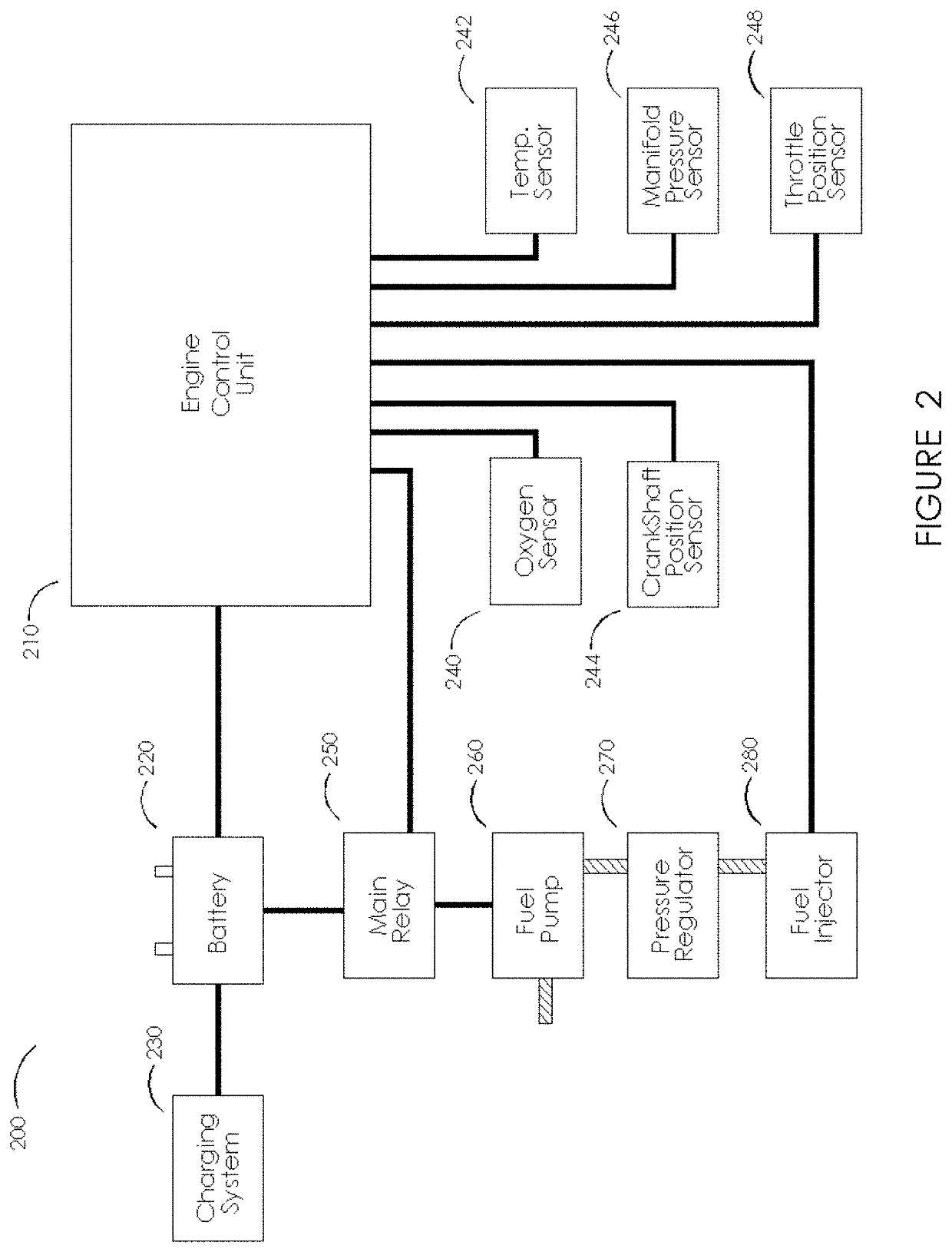
[0039]In one aspect, the invention aims to provide for all the benefits of EFI, but at system costs no more than—and preferably less than—products using carburetors for fuel metering. In one embodiment, the invention provides a system for metering air and fuel that uses software to implement the functions of at least some mechanical elements found in carburetors. In one embodiment, systems of the present invention employ new engine state measurement metrics as logical inputs to a logic unit operating (e.g., as software and / or firmware) in a processor such as a microprocessor or field programmable gate array (FPGA). Systems and methods of the present disclosure are lower in cost, simpler to physically configure, and more accurate and reliable than mechanical carburetors.

[0040]In one embodiment, the invention combines the elements of fuel pump and injector into a single subsystem which can operate at reduced pressures compared to existing EFI systems, providing for AFR management with...


PUM


Abstract

A fuel metering system for an internal combustion engine having a fuel injection timing unit to indicate a timepoint during one or more engine strokes, a fuel metering element have a predetermined full stroke volume for metering fuel into an air-fuel mixing location during one or more of the engine strokes, and a fuel metering element controller to control the delivery of fuel by causing the fuel metering element to deliver one of a full stroke volume and a fraction of a full stroke volume to achieve a desired AFR. In some embodiments, power generator circuitry is provided to harvest power from the ICE to power at least one of the fuel injection timing unit, the fuel metering element, and the fuel metering controller.

Description

CROSS-REFERENCE TO RELATED APPLICATIONS[0001]This application is a continuation application of U.S. application Ser. No. 17 / 033,661, filed Sep. 25, 2020, which claims the priority benefit of U.S. Provisional Application Ser. No. 62 / 906,701, filed Sep. 26, 2019. This application claims the priority benefit of both of the foregoing applications, which are each hereby incorporated by reference in their entirety.TECHNICAL FIELD[0002]The present invention relates to the field of air and fuel metering at the induction (i.e., intake) of internal combustion engines. More particularly, it involves improved fuel metering systems and methods to ensure efficient metering, mixing, and combustion of fuel and air in internal combustion engines (ICEs).BACKGROUND OF THE INVENTION[0003]ICEs typically use a reciprocating piston in a combustion chamber where combustion of oxygen and fuel mixtures occurs. The expansion of gases during the combustion cycle is then used to drive the piston to convert the ...

Claims


Application Information

Patent Timeline
Patent Type & Authority Applications(United States)
IPC IPC(8): F02D19/02F02D41/14F02D41/00F02D41/32F02D41/24
CPCF02D19/023F02D41/1445F02D19/029F02D41/3082F02D41/32F02D41/2454F02D41/0027F02D11/106F02D31/002F02D31/007F02D41/0002F02D41/1406F02D41/1475F02D41/1486F02D2200/10F02D2200/101F02D41/1497F02D2200/0625Y02T10/40
Inventor COLBORN, JOHN CRAIG
Owner SETAYSHA TECHNICAL SOLUTIONS LLC
Learn More