Tire vulcanization mold and pneumatic tire

a technology of pneumatic tires and molds, which is applied in the direction of tires, vehicle components, domestic applications, etc., can solve the problems of inability to provide the effect of suppressing the rubber from being caught at the fitting portion, the position and shape of the protrusion have not been studied in detail, etc., to achieve the effect of suppressing the rubber from being caught, maintaining the aesthetic appearance of the tire, and suppressing the occurrence of poor appearance of the pneumatic tir

Inactive Publication Date: 2021-12-09
TOYO TIRE & RUBBER CO LTD
View PDF3 Cites 0 Cited by
  • Summary
  • Abstract
  • Description
  • Claims
  • Application Information

AI Technical Summary

Benefits of technology

The present invention provides a tire vulcanization mold that can prevent poor appearance of a pneumatic tire caused by rubber being caught during molding. This mold maintains the aesthetic appearance of the tire and ensures quality production.

Problems solved by technology

However, the position and shape of the protrusion has not been studied in detail so as to suppress rubber from flowing to the fitting portion of the molds.
If the recess is provided extremely far from the fitting portion, the recess does not affect the flow of the rubber toward the fitting portion, and the effect of suppressing the rubber from being caught at the fitting portion cannot be provided.

Method used


Image

  • Tire vulcanization mold and pneumatic tire
  • Tire vulcanization mold and pneumatic tire
  • Tire vulcanization mold and pneumatic tire

Examples


Embodiment Construction

[0027]Hereinafter, embodiments of the present invention will be described with reference to the accompanying drawings.

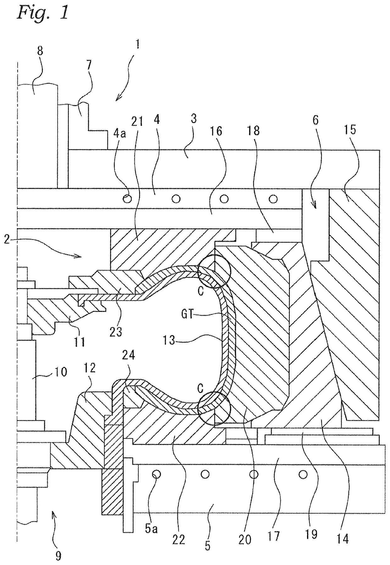
[0028]FIG. 1 shows a state in which a tire vulcanization mold 2 according to the present embodiment is attached to a vulcanization molding machine 1. The tire vulcanization mold 2 is attached via a container 6 between an upper plate 3 and an upper platen 4 of the vulcanization molding machine 1, and a lower platen 5.

[0029]The upper plate 3 is fixed to the lower end of a lifting cylinder 7. A lifting rod 8 is disposed at the center of the lifting cylinder 7. The upper platen 4 is fixed to the lower end of the lifting rod 8. The lifting cylinder 7 and the lifting rod 8 are moved up and down by a driving device (not shown). The upper plate 3 and the upper platen 4 are configured to be able to move up and down independently. A flow path 4a is formed in the upper platen 4. The temperature can be adjusted by the flow of a heat exchange medium (for example, oil) in the flow...


PUM

PropertyMeasurementUnit
distanceaaaaaaaaaa
radiusaaaaaaaaaa
width W1aaaaaaaaaa

Abstract

A tire vulcanization mold including a sector mold divided into a plurality of pieces along a circumferential direction of a green tire, the sector mold configured to vulcanization mold a tread portion of the green tire into a predetermined shape, and an upper mold and a lower mold disposed on both sides of the green tire so as to sandwich the green tire therebetween in an axial direction of the green tire, the upper mold and the lower mold configured to vulcanization mold a side portion of the green tire into a predetermined shape. The sector mold has a relief groove in a vicinity of a fitting portion between the sector mold, and the upper mold and the lower mold.

Description

CROSS-REFERENCE TO RELATED APPLICATIONS[0001]The application is a Divisional of U.S. patent application Ser. No. 16 / 356,102, filed on Mar. 18, 2019, which is a Divisional of U.S. patent application Ser. No. 15 / 730,122, filed on Oct. 11, 2017, which claims priority of Japanese Patent Application No. 2016-244692 filed on Dec. 16, 2016, the content of which is incorporated herein by reference.BACKGROUND OF THE INVENTIONTechnical Field[0002]The present invention relates to a tire vulcanization mold and a pneumatic tire.Related Art[0003]In vulcanization molding of a pneumatic tire, two kinds of molds corresponding to molded portions are generally used. One is a mold for molding a tread portion of the tire, which is called a sector mold. The other is a mold for molding a sidewall portion over a shoulder portion of the tire, which is called a side mold. The sector mold is divided into a plurality of pieces and arranged in the circumferential direction of the tire, and the side mold is arra...

Claims


Application Information

Patent Timeline
Patent Type & Authority Applications(United States)
IPC IPC(8): B29D30/06
CPCB29D30/0629B29D30/0662B29D2030/063B29D2030/0612B29D2030/0667B29D30/0606B60C5/00
Inventor UENO, TOMONORI
Owner TOYO TIRE & RUBBER CO LTD
Why Eureka
Try Eureka