Breathing zone ventillation system

a ventillation system and breathing zone technology, applied in ventilation systems, lighting and heating apparatus, heating types, etc., can solve the problems of inability to reliably prevent the improvement of room ventilation, the technology of killing ions is not good, and the ability to keep fresh coughed or sneezed air in a large congregate setting, etc., to achieve high velocity

Inactive Publication Date: 2021-11-11
HENWOOD GERARD STEPHEN
View PDF16 Cites 1 Cited by
  • Summary
  • Abstract
  • Description
  • Claims
  • Application Information

AI Technical Summary

Benefits of technology

The invention is a breathing zone ventilation system that provides a protective air barrier between close individuals within a local environment. It includes an air inlet, a blower, and at least one air tray stage. The air tray stage has a frame with multiple baffles which create a labyrinth pathway between the blower and the outlet. The system can be used in places like restaurants or offices to protect customers from airborne diseases or pollutants. It can be mounted on a table or floor and can be easily moved around. The invention helps to provide a safe and healthy environment for close contact between individuals.

Problems solved by technology

Room and building ventilation is considered a viable way to disperse the virus, but it is also the cause of its spread.
All of this proves that room ventilation is the culprit in spreading germs from one person to another and that there is no way that improvements to room ventilation can be reliably prevent airborne transmission of disease.
There is plenty of time when air systems, based on room temperature are not producing mechanically blown heated or cooled air, thereby not ridding the air of infectious diseases during those times. Technologies claiming to charge the air with infection-killing ions have little testing in way of keeping freshly coughed or sneezed air from infecting a nearby person.
While effective in the space of two people, this technology, is not viable in a larger congregate setting since the air flow launches infectious aerosols about the room causing them to be transmitted to a person other than the two people at the table, and arguably even to the persons at the table when the air moves about the room and recirculates to either person from any position behind the air curtain.

Method used


Image

  • Breathing zone ventillation system
  • Breathing zone ventillation system
  • Breathing zone ventillation system

Examples


Embodiment Construction

[0038]The following detailed description is of the best currently contemplated modes of carrying out exemplary embodiments of the invention. The description is not to be taken in a limiting sense but is made merely for the purpose of illustrating the general principles of the invention.

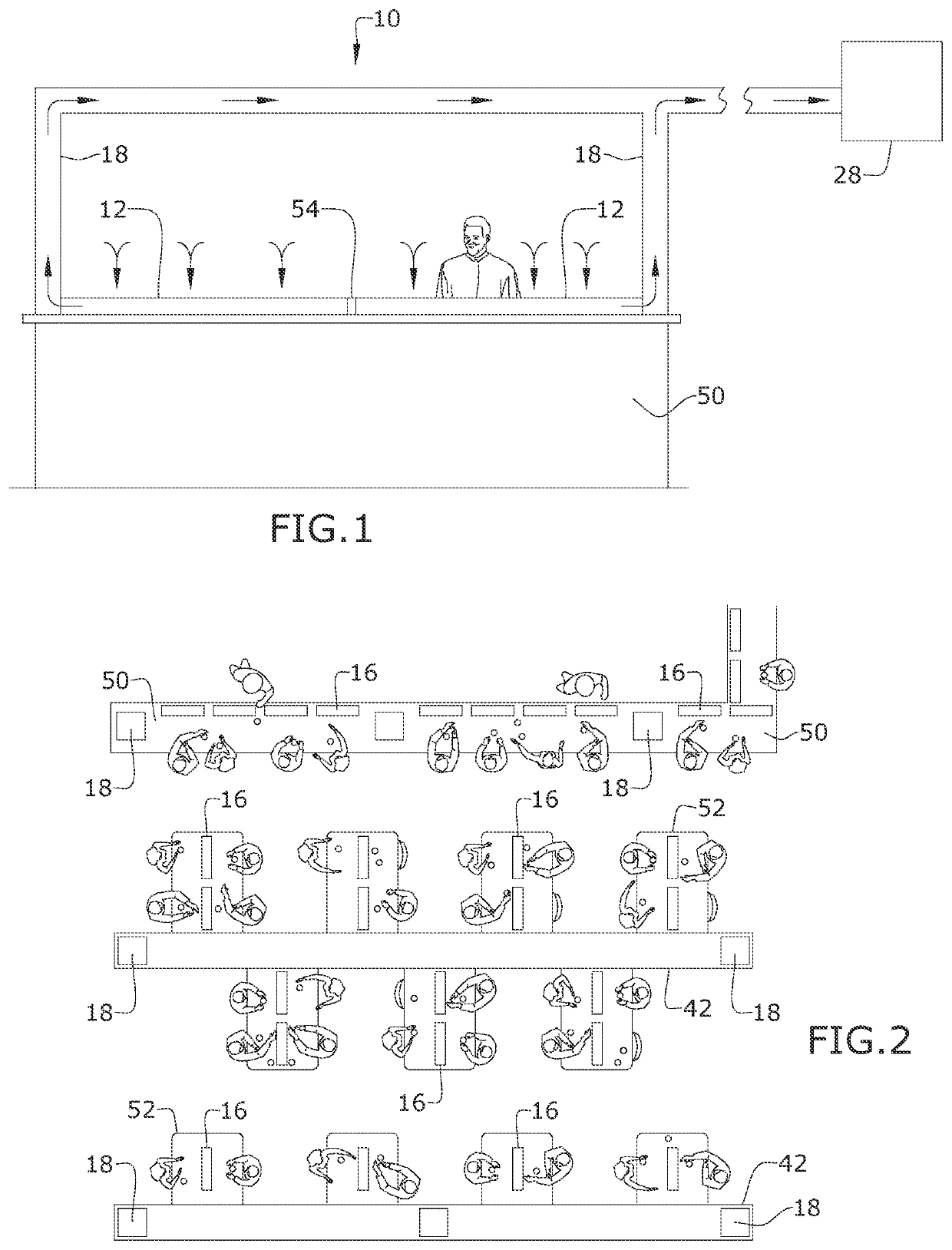
[0039]Broadly, embodiments of the present invention provide a breathing zone ventilation system that provides an air barrier for reducing the spread of airborne pathogens. The breathing zone ventilation (BZV) system provides for a protective air barrier between closely spaced occupants of an enclosed space, while preventing the dispersal of airborne contaminants within that same enclosed space.

[0040]As seen in reference to the drawings of FIGS. 1 through 14, the breathing zone ventilation system of the present invention may be employed with furnishings commonly utilized in various applications and settings. Preferably, the breathing zone ventilation system 10 is employed within an enclosed space where...


PUM


Abstract

A breathing zone ventilation system for providing a protective air barrier between closely spaced individuals within a local environment. The breathing zone ventilation system includes a plurality of seats. An air control module has a housing defining an interior cavity, a blower, and at least one air tray stage. The housing has an inlet in communication with an air inlet and outlet. The blower, contained within the housing, is configured to develop a high velocity airflow into the air inlet, defining a downdraft air curtain. The at least one air tray stage is disposed between the blower and the outlet and has a frame defining an air tray enclosure. A plurality of baffles are disposed in a spaced apart relation within the air tray enclosure to define a labyrinth pathway between the blower and the outlet. The outlet may be configured to vent clean air within the local environment.

Description

CROSS-REFERENCE TO RELATED APPLICATION[0001]This application claims the benefit of priority of U.S. provisional application No. 63 / 101,632 filed May 9, 2020, and Ser. No. 63 / 103,533 filed Aug. 10, 2020, the contents of which are herein incorporated by reference.BACKGROUND OF THE INVENTION[0002]The present invention relates to air barrier protection systems, and more particularly to air barrier protection systems provided in closed environments.[0003]COVID 19 made all the world's people aware of just how dangerously vulnerable we are when it comes to invisible viruses that are spread by breathing, coughing, sneezing, speaking and singing, both indoors and outdoors. The global reaction was to isolate and distance people from each other and to shut down or reduce capacity in any public space where people congregate. Room and building ventilation is considered a viable way to disperse the virus, but it is also the cause of its spread.[0004]Direction of airflow in a room, is largely dict...

Claims


Application Information

Patent Timeline
IPC IPC(8): F24F9/00
CPCF24F9/00F24F8/108F24F2009/002F24F7/003F24F13/0604
Inventor HENWOOD, GERARD STEPHEN
Owner HENWOOD GERARD STEPHEN
Why Eureka
Try Eureka