
Method for manufacturing a single crystal by solution growth enabling trapping of parasitic crystals

a technology of growth solution and manufacturing method, which is applied in the direction of single crystal growth, polycrystalline material growth, after-treatment, etc., can solve the problems of parasitic crystals in growth solution, reduce the mass accessible to the main crystal, and trap parasitic crystals, so as to simplify the equipment necessary and limit the effect of crystal nucleation

Pending Publication Date: 2021-11-11
COMMISSARIAT A LENERGIE ATOMIQUE ET AUX ENERGIES ALTERNATIVES
View PDF0 Cites 0 Cited by
  • Summary
  • Abstract
  • Description
  • Claims
  • Application Information

AI Technical Summary

Benefits of technology

The present invention aims to prevent the formation of unwanted crystals in a growing solution. It does this by using a liquid that doesn't mix with the solution and is denser than it. The interface between the solution and the liquid is positioned below the lowest point where the single crystal is growing, which allows the unwanted crystals to escape gravity and be trapped below. This process ensures that the effects of nucleation are limited and prevents the growth of unwanted bubbles or seeds in the solution.

Problems solved by technology

Indeed, the consumption of salt in solution by a parasitic crystal reduces the mass accessible to the main crystal.
Regardless of the nature of nucleation, the appearance of parasitic crystals in the growth solution is a cause of failure when growing large single crystals.
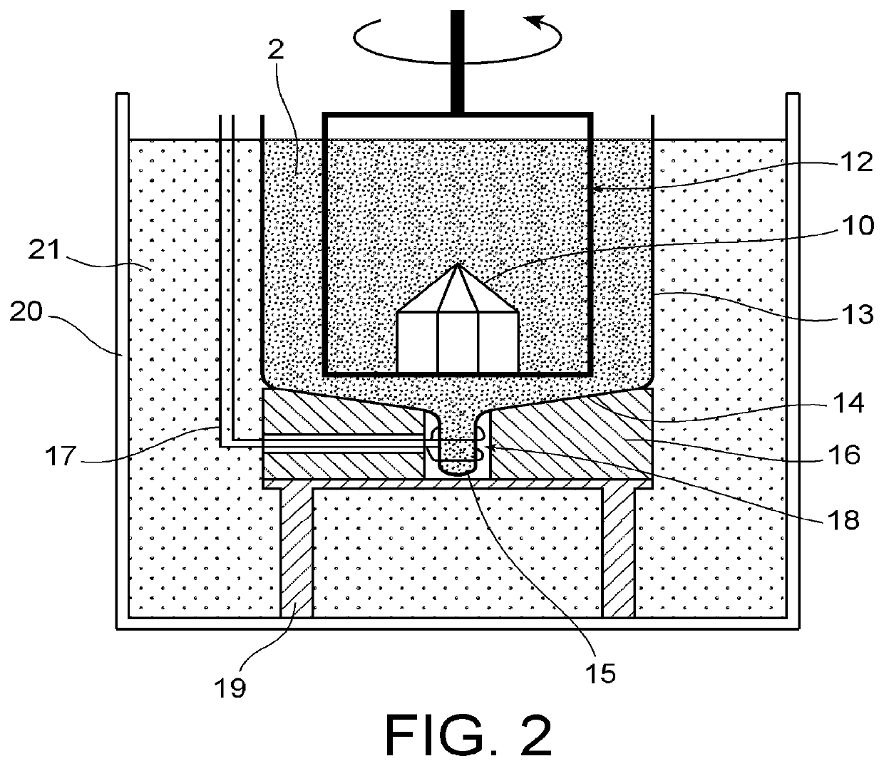
Indeed, any parasitic crystals that form during growth will move toward the well due to the curvature of the bottom and get trapped there due to the higher temperature therein.
The disadvantage of this solution is that it requires special equipment, and in particular a vessel with a bottom with a protruding part, a heating means and a thermal insulation plate.

Method used


Image

  • Method for manufacturing a single crystal by solution growth enabling trapping of parasitic crystals
  • Method for manufacturing a single crystal by solution growth enabling trapping of parasitic crystals
  • Method for manufacturing a single crystal by solution growth enabling trapping of parasitic crystals

Examples


Embodiment Construction

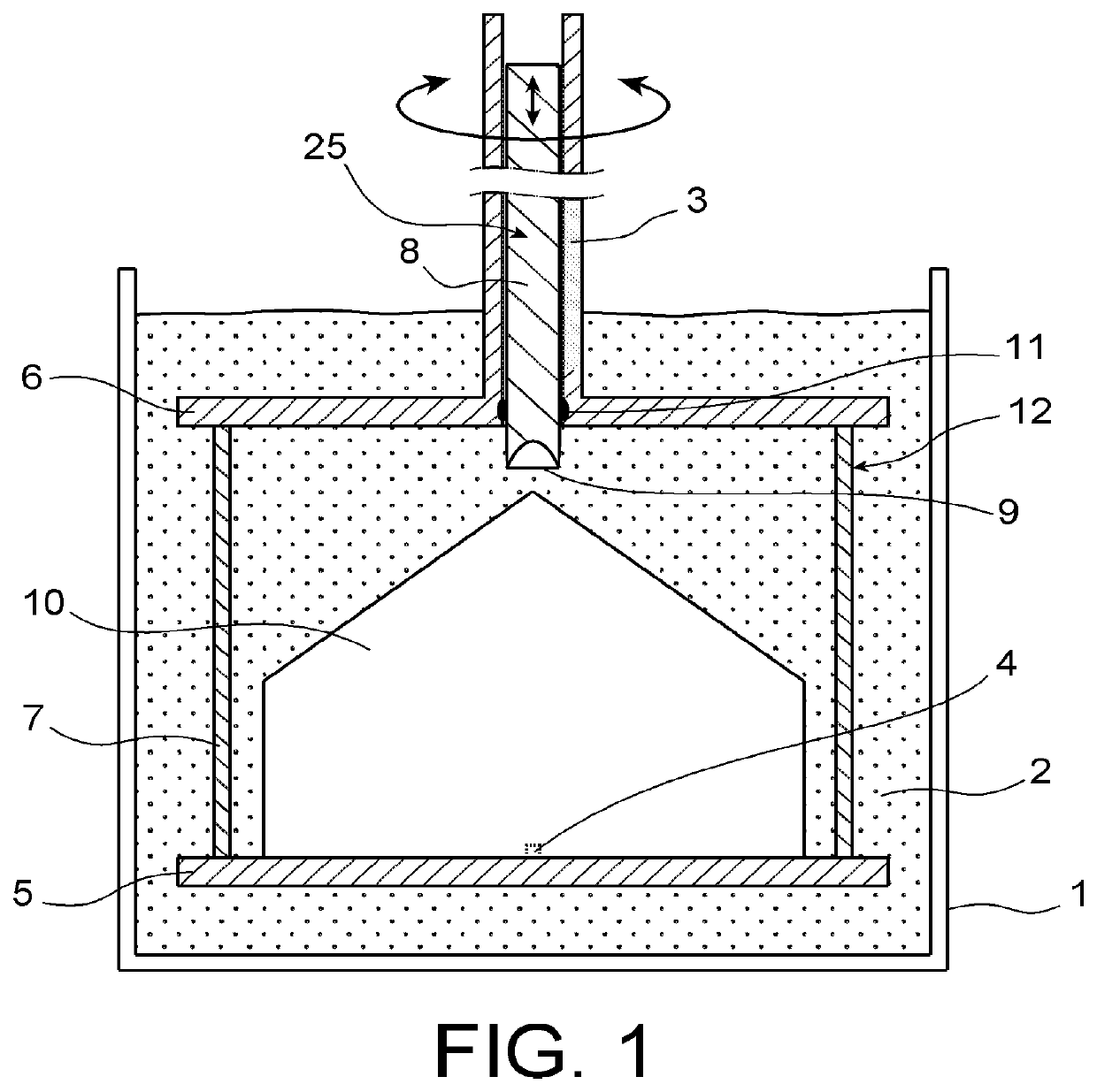
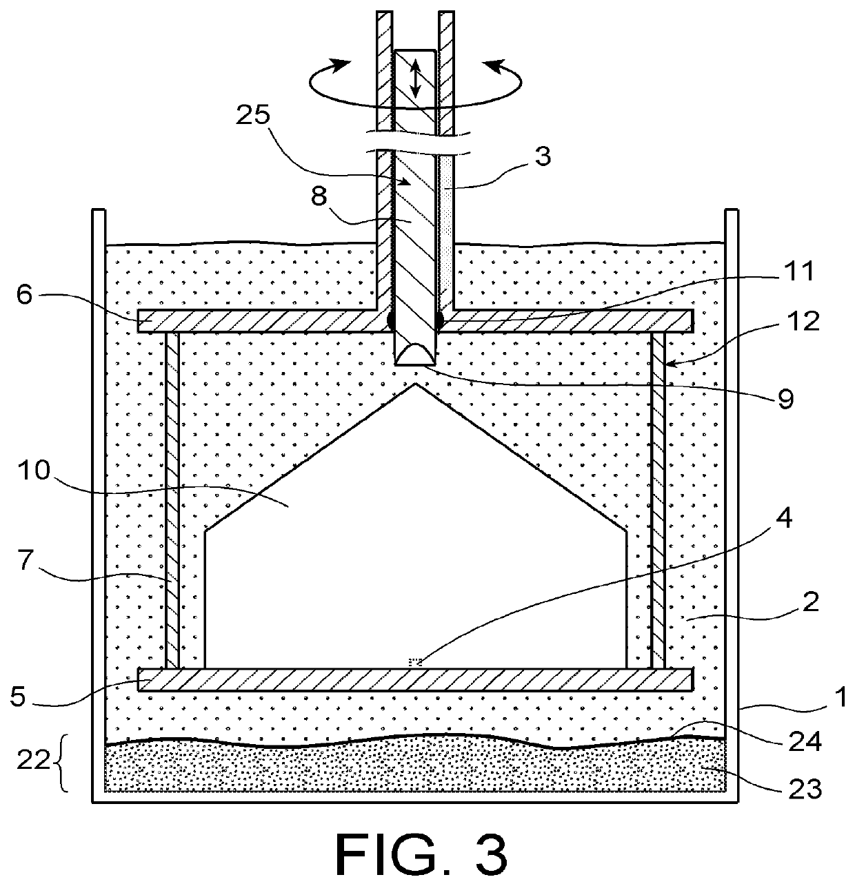
[0050]An example of a growth installation with which the process according to the invention can be implemented is shown in FIG. 3. The installation is the same as the one described in FIG. 1. There is thus, in the vessel 1, a growth platform 12, a growth solution 2 and a growing crystal 10. The growth solution 2 and the growing crystal 10 form respectively a first phase (liquid) and a second phase (solid). In accordance with the process according to the invention, a liquid 21, which is immiscible with the growth solution 2, is also introduced into the vessel; thus the vessel 1 also contains a third phase (liquid), which forms a trapping zone 22 for the parasitic crystals.

[0051]The density of this immiscible liquid 21 is chosen higher than that of the growth solution 2, so that it covers the bottom of the vessel 1. Furthermore, the amount of immiscible liquid introduced into the vessel is such that the interface 24 between the immiscible liquid 21 and the growth solution 2 is located...


PUM

PropertyMeasurementUnit
temperatureaaaaaaaaaa
densityaaaaaaaaaa
chemical compositionaaaaaaaaaa

Abstract

A method for manufacturing a single crystal may be by solution growth from a seed crystal, in a unit including a tank and a growth platform having a lower plate. The method may include: fastening the seed to the lower plate; introducing a crystallization solution of density dS into the tank; treating the solution in order to render it supersaturated; bringing the seed into contact with the supersaturated solution; rotating the platform until the single crystal is obtained. Before bringing the seed into contact with the supersaturated solution, the method may include forming, in the tank, of a zone for trapping parasitic crystals of density dC by introducing, into the tank, a liquid, immiscible with the growth solution, of density d>dS and d<dc, which forms with the growth solution an interface located below the lower plate.

Description

TECHNICAL FIELD[0001]The field of the invention is that of the production of single crystals by solution growth from a seed crystal.[0002]The invention relates more particularly to a process limiting the effects of primary or secondary nucleation in a crystal growth solution, in the context of the production of single crystals by growth in saline solution.BACKGROUND ART[0003]Single crystals, and in particular large single crystals of potassium dihydrogen phosphate (KDP) or deuterated potassium dihydrogen phosphate (DKDP), are obtained by crystal growth from a seed (i.e., the initial crystal from which growth begins) placed in a supersaturated solution of a salt of the same nature as the seed. Plates, cut from these large KDP and DKDP single crystals, can be used to make optical elements for power lasers for inertial confinement fusion. These optical elements are for example Pockels cells or optical elements for frequency conversion, such as frequency doublers (SHG) or triplers (THG)...

Claims


Application Information

Patent Timeline
Patent Type & Authority Applications(United States)
IPC IPC(8): C30B7/00C30B29/14C30B35/00
CPCC30B7/00C30B35/007C30B29/14
Inventor PINTAULT, BRUNOBELOUET, CHRISTIAN
Owner COMMISSARIAT A LENERGIE ATOMIQUE ET AUX ENERGIES ALTERNATIVES
Learn More